Part 2
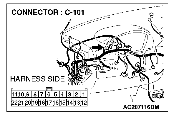
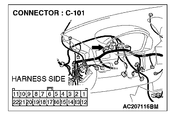
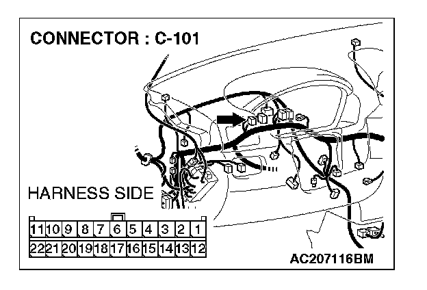
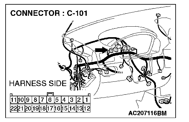
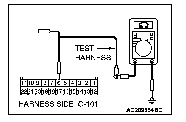
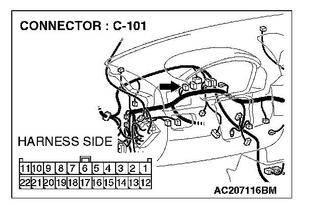
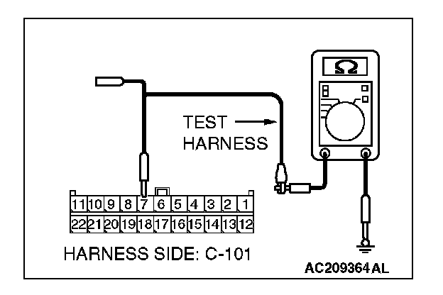
STEP 25. Check the CAN_H line (communication line including the steering wheel sensor) between joint connector (4) and steering wheel sensor connector for short to ground. Measure the resistance at joint connector (4) C-101.CAUTION:
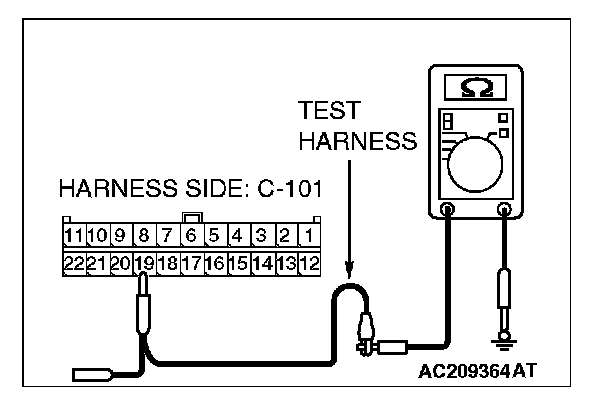
- A digital multimeter should be used.
- The test wiring harness should be used.
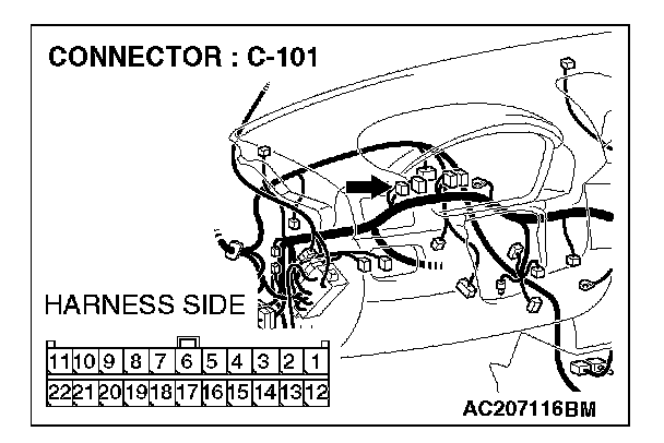
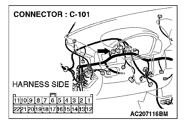
1. Disconnect joint connector (4) C-101, and measure the resistance at the wiring harness side of joint connector (4) C-101.
2. Turn the ignition switch to the "LOCK" (OFF) position.
CAUTION: Disconnect the negative battery terminal.
3. Disconnect the negative battery terminal.
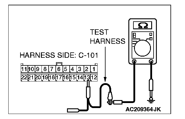
4. Measure the resistance between joint connector (4) terminal 13 and body ground.
OK: 1 kohm or more
Q: Does the resistance measure 1 kohm or more?
YES:
NO:
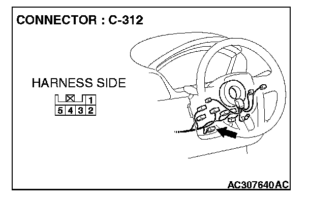
STEP 26. Check steering wheel sensor connector C-312 for loose, corroded or damaged terminals, or terminals pushed back in the connector.
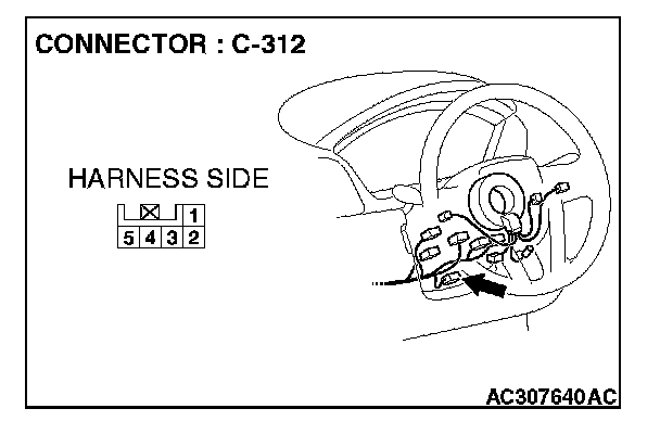
CAUTION: The strand end of the twist wire should be within 10 cm (4 inches) from the connector.
Q: Is steering wheel sensor connector C-312 in good condition?
YES: Go to Step 27.
NO: Repair the damaged parts.
STEP 27. Check the CAN_H line (communication line only) between joint connector (4) and steering wheel sensor connector for short to ground. Measure the resistance at joint connector (4) C-101.
CAUTION:
- A digital multimeter should be used.
- The test wiring harness should be used.
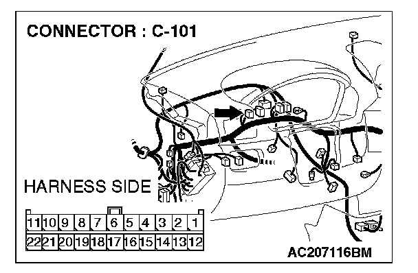
1. Disconnect joint connector (4) C-101 and steering wheel sensor connector C-312, and measure the resistance at the wiring harness side of joint connector (4) C-101.
2. Turn the ignition switch to the "LOCK" (OFF) position.
CAUTION: Disconnect the negative battery terminal.
3. Disconnect the negative battery terminal.
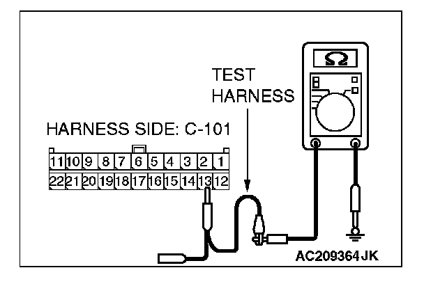
4. Measure the resistance between joint connector (4) terminal 13 and body ground.
OK: 1 kohm or more
CAUTION: Strictly observe the specified wiring harness repair procedure.
Q: Does the resistance measure 1 kohm or more?
YES:
NO:
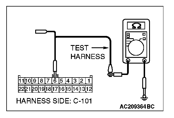
STEP 28. Check the CAN_H line (communication line including the multi-center display unit (middle-grade type or vehicles with Mitsubishi multi communication system)) between joint connector (4) and multi-center display connector for short to ground. Measure the resistance at joint connector (4) C-101.
CAUTION:
- A digital multimeter should be used.
- The test wiring harness should be used.

1. Disconnect joint connector (4) C-101, and measure the resistance at the wiring harness side of joint connector (4) C-101.
2. Turn the ignition switch to the "LOCK" (OFF) position.
CAUTION: Disconnect the negative battery terminal.
3. Disconnect the negative battery terminal.
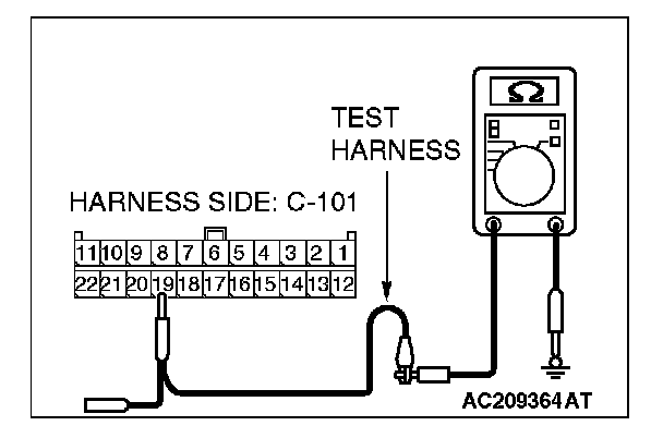
4. Measure the resistance between joint connector (4) terminal 19 and body ground.
OK: 1 kohm or more
Q: Does the resistance measure 1 kohm or more?
YES:
NO:
STEP 29. Check multi-center display unit (middle-grade type or vehicles with Mitsubishi multi communication system) connector C-06
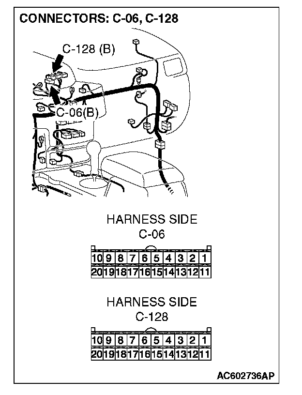
CAUTION: The strand end of the twist wire should be within 10 cm (4 inches) from the connector.
Q: Is multi-center display unit (middle-grade type or vehicles with Mitsubishi multi communication system) connector C-06
YES: Go to Step 30.
NO: Repair the damaged parts.
STEP 30. Check the CAN_H line (communication line only) between joint connector (4) and multi-center display unit(middle-grade type or vehicles with Mitsubishi multicommunication system) connector for short to ground. Measure the resistance at joint connector (4) C-101.
CAUTION:
- A digital multimeter should be used.
- The test wiring harness should be used.
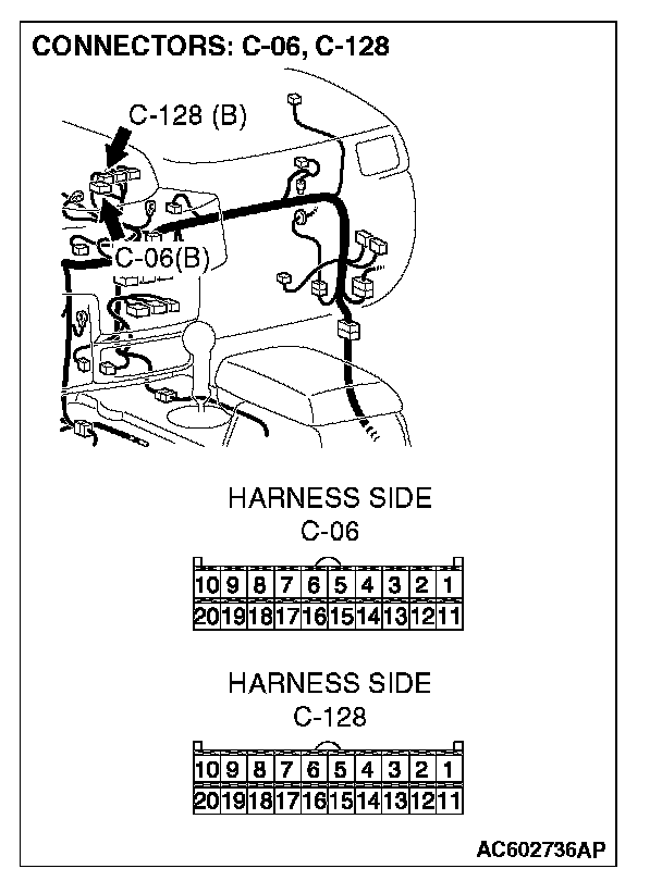
1. Disconnect joint connector (4) C-101 and multi-center display unit (middle-grade type or vehicles with Mitsubishi multi communication system) connector C-06
2. Turn the ignition switch to the "LOCK" (OFF) position.
CAUTION: Disconnect the negative battery terminal.
3. Disconnect the negative battery terminal.
4. Measure the resistance between joint connector (4) terminal 19 and body ground.
OK: 1 kohm or more
CAUTION: Strictly observe the specified wiring harness repair procedure.
Q: Does the resistance measure 1 kohm or more?
YES:
NO:
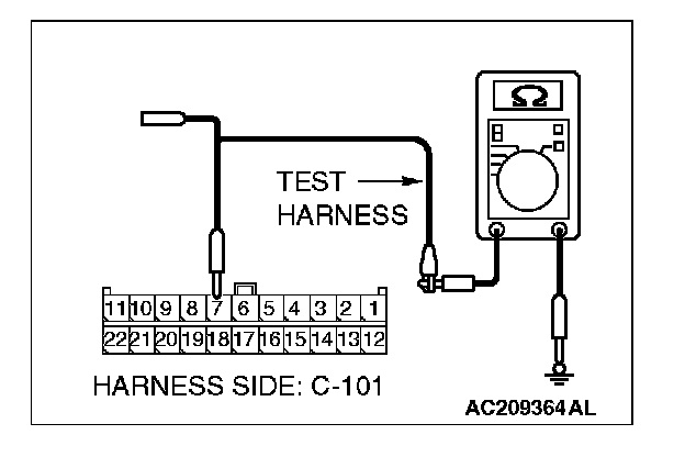
STEP 31. Check the CAN_H line (communication line only) between joint connector (4) and the data link connector for short to ground. Measure the resistance at joint connector (4) C-101.
CAUTION:
- A digital multimeter should be used.
- The test wiring harness should be used.
1. Disconnect joint connector (4) C-101, and measure the resistance at the wiring harness side of joint connector (4) C-101.
2. Turn the ignition switch to the "LOCK" (OFF) position.
CAUTION: Disconnect the negative battery terminal.
3. Disconnect the negative battery terminal.
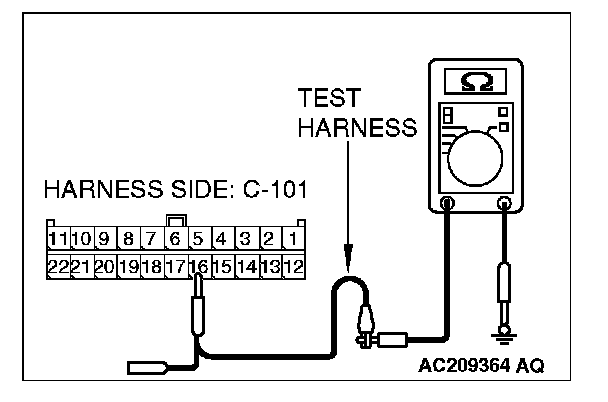
4. Measure the resistance between joint connector (4) terminal 16 and body ground.
OK: 1 kohm or more
CAUTION: Strictly observe the specified wiring harness repair procedure.
Q: Does the resistance measure 1 kohm or more?
YES:
NO:
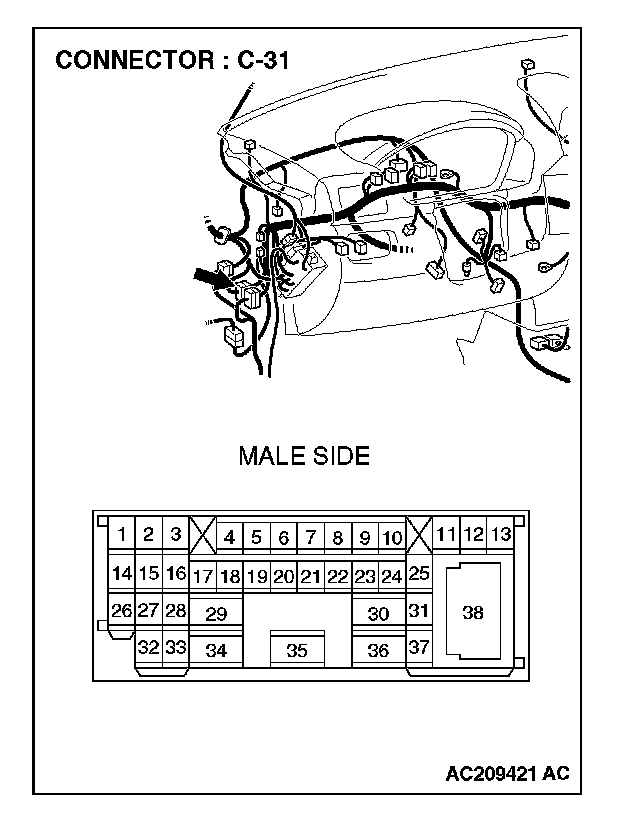
STEP 32. Check the CAN_H line (communication line only) between intermediate connector C-31 and joint connector (4) for short to ground. Measure the resistance at joint connector (4) C-101.
CAUTION:
- A digital multimeter should be used.
- The test wiring harness should be used.
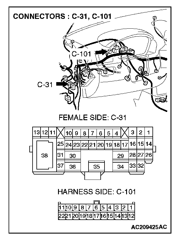
1. Disconnect intermediate connector C-31 and joint connector (4) C-101, and measure the resistance at the wiring harness side of joint connector (4) C-101.
2. Turn the ignition switch to the "LOCK" (OFF) position.
CAUTION: Disconnect the negative battery terminal.
3. Disconnect the negative battery terminal.
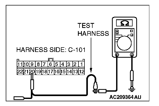
4. Measure the resistance between joint connector (4) terminal 20 and body ground.
OK: 1 kohm or more
CAUTION: Strictly observe the specified wiring harness repair procedure.
Q: Does the resistance measure 1 kohm or more?
YES:
NO:
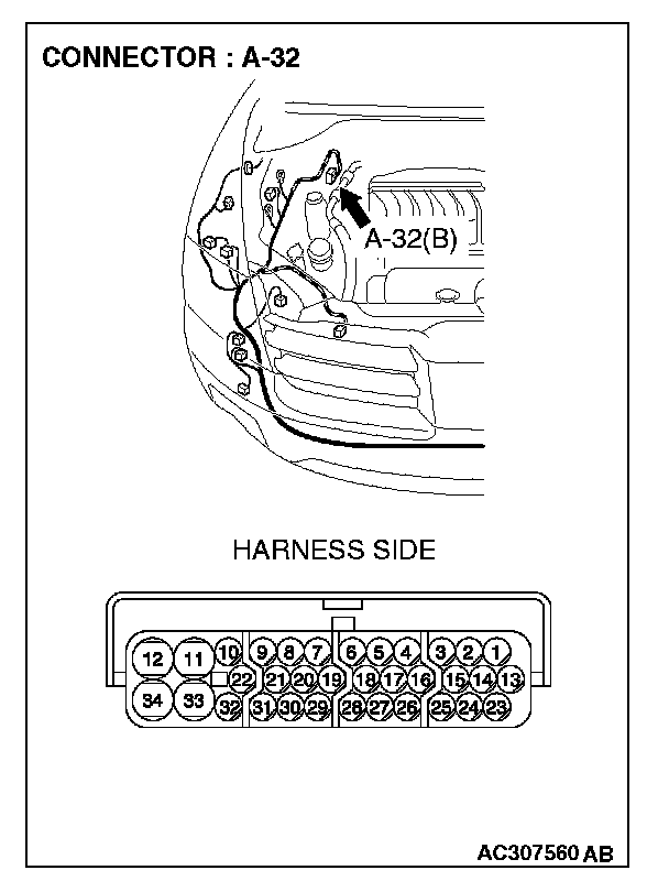
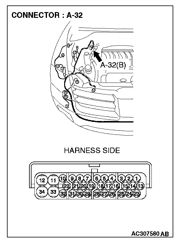
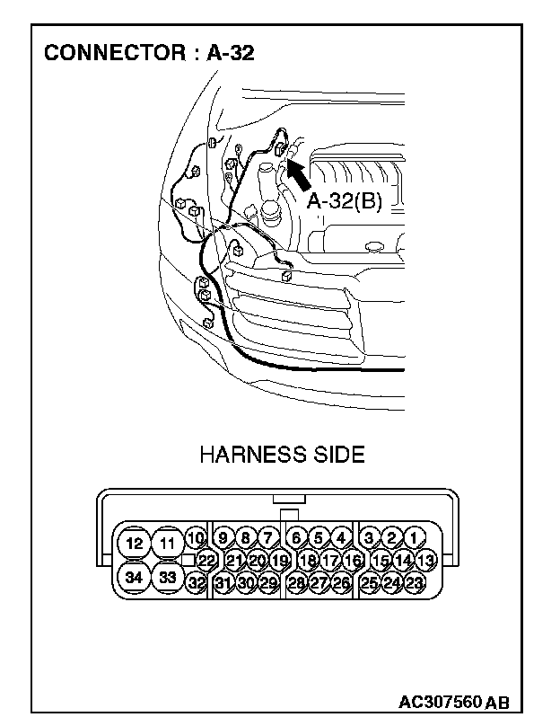
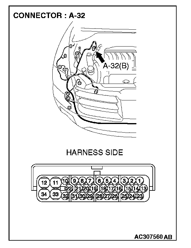
STEP 33. Check ASC/TCL-ECU connector A-32 for loose, corroded or damaged terminals, or terminals pushed back in the connector.
CAUTION: The strand end of the twist wire should be within 10 cm (4 inches) from the connector.
Q: Is ASC/TCL-ECU connector A-32 in good condition?
YES: Go to Step 34.
NO: Repair the damaged parts.
STEP 34. Check the CAN_H line (communication line only) between intermediate connector C-31 and ASC/TCL-ECU connector for short to ground. Measure the resistance at intermediate connector C-31.
CAUTION:
- A digital multimeter should be used.
- The test wiring harness should be used.
1. Disconnect intermediate connector C-31 and ASC/TCL-ECU connector A-32, and measure the resistance at the male side of intermediate connector C-31(at front wiring harness side).
2. Turn the ignition switch to the "LOCK" (OFF) position.
CAUTION: Disconnect the negative battery terminal.
3. Disconnect the negative battery terminal.
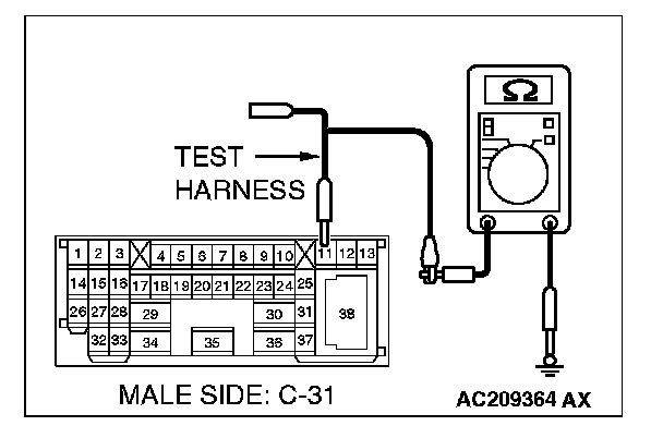
4. Measure the resistance between intermediate connector C-31 terminal 11 and body ground.
OK: 1 kohm or more
CAUTION: Strictly observe the specified wiring harness repair procedure.
Q: Does the resistance measure 1 kohm or more?
YES:
NO:
STEP 35. Check the CAN_H line (communication line only) between the powertrain control module connector and ASC/TCL-ECU connector for short to ground. Measure the resistance at powertrain control module connector B-18.
CAUTION:
- A digital multimeter should be used.
- The test wiring harness should be used.
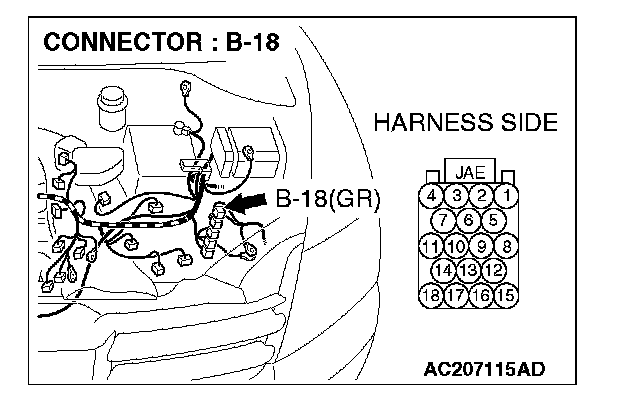
1. Disconnect powertrain control module connector B-18 and ASC/TCL-ECU connector A-32, and measure the resistance at the harness side of powertrain control module connector B-18.
2. Turn the ignition switch to the "LOCK" (OFF) position.
CAUTION: Disconnect the negative battery terminal.
3. Disconnect the negative battery terminal.
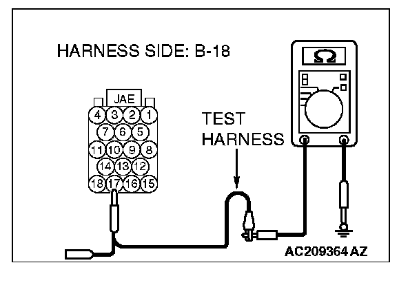
4. Measure the resistance between powertrain control module connector terminal 17 and body ground.
OK: 1 kohm or more
CAUTION: Strictly observe the specified wiring harness repair procedure.
Q: Does the resistance measure 1 kohm or more?
YES:
NO:
STEP 36. Check the CAN_H line inside the ASC/TCL-ECU for short to ground. Measure the resistance at ASC/TCL-ECU connector A-32.
CAUTION:
- A digital multimeter should be used.
- The test wiring harness should be used.
1. Disconnect ASC/TCL-ECU connector A-32.
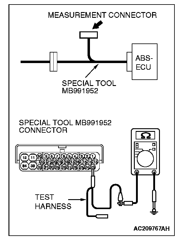
2. Connect special tool MB991952 (ABS check harness) to the ASC/TCL-ECU and the wiring harness, and measure the resistance at special tool MB991952 (ABS check harness).
3. Turn the ignition switch to the "LOCK" (OFF) position.
CAUTION: Disconnect the negative battery terminal.
4. Disconnect the negative battery terminal.
5. Measure the resistance between special tool MB991952(ABS check harness) connector terminal 23 and body ground.
OK: 1 kohm or more
Q: Does the resistance measure 1 kohm or more?
YES:
NO:
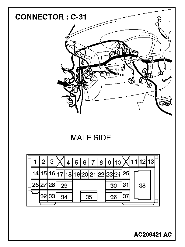
STEP 37. Check intermediate connector C-31 for loose, corroded or damaged terminals, or terminals pushed back in the connector.
CAUTION: The strand end of the twist wire should be within 10 cm (4 inches) from the connector.
Q: Is intermediate connector C-31 in good condition?
YES: Go to Step 38.
NO: Repair the damaged parts.
STEP 38. Check the CAN_L-side bus line (communication line including ECUs) of the front wiring harness for short to ground. Measure the resistance at intermediate connector C-31.
CAUTION:
- A digital multimeter should be used.
- The test wiring harness should be used.
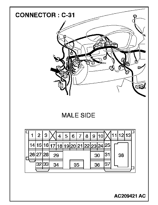
1. Disconnect intermediate connector C-31, and measure the resistance at the male side (at front wiring harness side).
2. Turn the ignition switch to the "LOCK" (OFF) position.
CAUTION: Disconnect the negative battery terminal.
3. Disconnect the negative battery terminal.
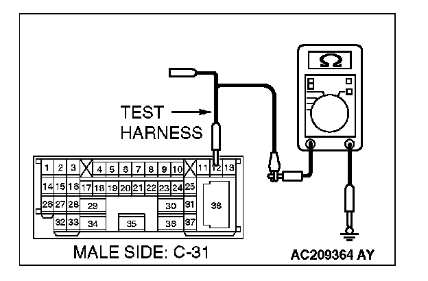
4. Measure the resistance between intermediate connector C-31 terminal 12 and body ground.
OK: 1 kohm or more
Q: Does the resistance measure 1 kohm or more?
YES:
NO:
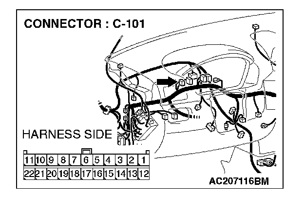
STEP 39. Check joint connector (4) C-101 for loose, corroded or damaged terminals, or terminals pushed back in the connector.
NOTE: For the removal of the joint connector, refer to "How To Disconnect Joint Connector".
CAUTION: The strand end of the twist wire should be within 10 cm (4 inches) from the connector.
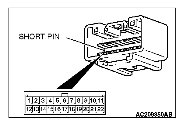
Check the joint connector at the wiring harness side for loose, corroded or damaged terminals, or terminals pushed back in the connector, and also check the short pin behind the connector for corrosion, deformation and delamination.
Q: Is joint connector (4) C-101 in good condition?
YES: Go to Step 40.
NO: Repair the damaged parts. Replace the joint connector as necessary.
STEP 40. Check the CAN_L line (communication line including the combination meter) between joint connector (4) and the combination meter connector for short to ground. Measure the resistance at joint connector (4) C-101.
CAUTION:
- A digital multimeter should be used.
- The test wiring harness should be used.

1. Disconnect joint connector (4) C-101, and measure the resistance at the wiring harness side of joint connector (4) C-101.
2. Turn the ignition switch to the "LOCK" (OFF) position.
CAUTION: Disconnect the negative battery terminal.
3. Disconnect the negative battery terminal.
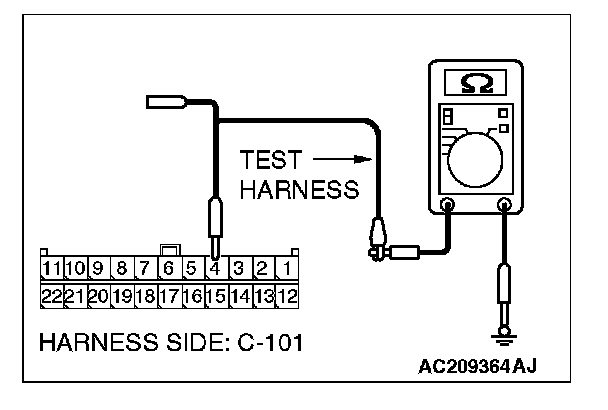
4. Measure the resistance between joint connector (4) terminal 4 and body ground.
OK: 1 kohm or more
Q: Does the resistance measure 1 kohm or more?
YES:
NO:
STEP 41. Check the CAN_L line (communication line only) between joint connector (4) and the combination meter connector for short to ground. Measure the resistance at joint connector (4) C-101.
CAUTION:
- A digital multimeter should be used.
- The test wiring harness should be used.
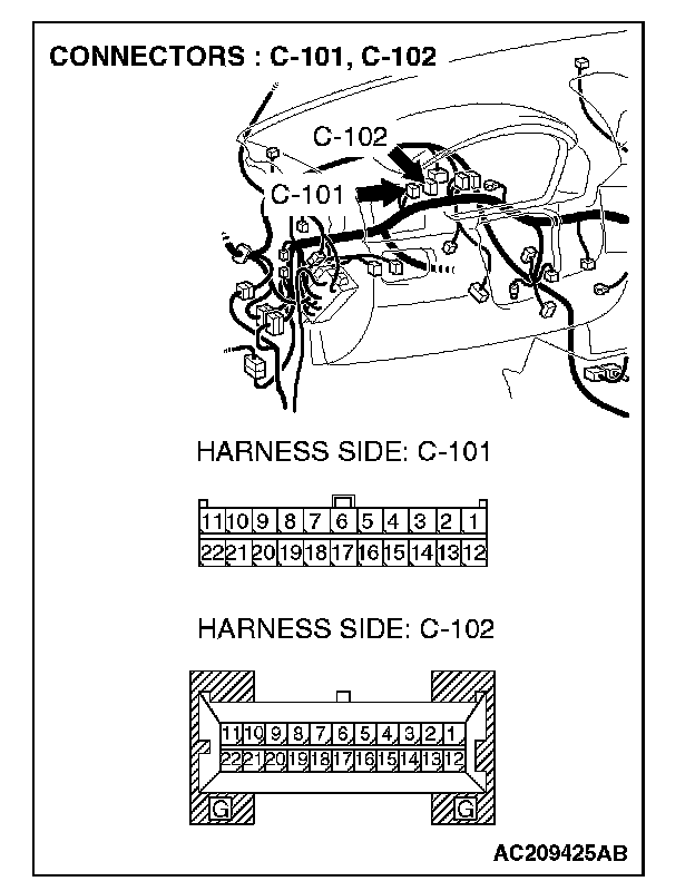
1. Disconnect joint connector (4) C-101 and combination meter connector C-102, and measure the resistance at the wiring harness side of joint connector (4) C-101.
2. Turn the ignition switch to the "LOCK" (OFF) position.
CAUTION: Disconnect the negative battery terminal.
3. Disconnect the negative battery terminal.
4. Measure the resistance between joint connector (4) terminal 4 and body ground.
OK: 1 kohm or more
CAUTION: Strictly observe the specified wiring harness repair procedure.
Q: Does the resistance measure 1 kohm or more?
YES:
NO:
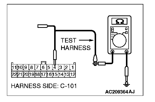
STEP 42. Check the CAN_L line (communication line including the ETACS-ECU) between joint connector (4) and the ETACS-ECU connector for short to ground. Measure the resistance at joint connector (4) C-101.
CAUTION:
- A digital multimeter should be used.
- The test wiring harness should be used.
1. Disconnect joint connector (4) C-101, and measure the resistance at the wiring harness side of joint connector (4) C-101.
2. Turn the ignition switch to the "LOCK" (OFF) position.
CAUTION: Disconnect the negative battery terminal.
3. Disconnect the negative battery terminal.
4. Measure the resistance between joint connector (4) terminal 6 and body ground.
OK: 1 kohm or more
Q: Does the resistance measure 1 kohm or more?
YES:
NO:
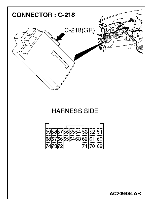
STEP 43. Check ETACS-ECU connector C-218 for loose, corroded or damaged terminals, or terminals pushed back in the connector.
CAUTION: The strand end of the twist wire should be within 10 cm (4 inches) from the connector.
Q: Is ETACS-ECU connector C-218 in good condition?
YES: Go to Step 44.
NO: Repair the damaged parts.
STEP 44. Check the CAN_L line (communication line only) between joint connector (4) and ETACS-ECU connector for short to ground. Measure the resistance at joint connector (4) C-101.
CAUTION:
- A digital multimeter should be used.
- The test wiring harness should be used.

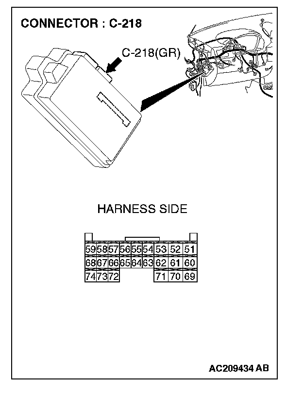
1. Disconnect joint connector (4) C-101 and ETACS-ECU connector C-218, and measure the resistance at the wiring harness side of joint connector (4) C-101.
2. Turn the ignition switch to the "LOCK" (OFF) position.
CAUTION: Disconnect the negative battery terminal.
3. Disconnect the negative battery terminal.
4. Measure the resistance between joint connector (4) terminal 6 and body ground.
OK: 1 kohm or more
CAUTION: Strictly observe the specified wiring harness repair procedure.
Q: Does the resistance measure 1 kohm or more?
YES:
NO:
STEP 45. Check the CAN_L line (communication line including the A/C-ECU) between joint connector (4) and the A/C-ECU connector for short to ground. Measure the resistance at joint connector (4) C-101.
CAUTION:
- A digital multimeter should be used.
- The test wiring harness should be used.
1. Disconnect joint connector (4) C-101, and measure the resistance at the wiring harness side of joint connector (4) C-101.
2. Turn the ignition switch to the "LOCK" (OFF) position.
CAUTION: Disconnect the negative battery terminal.
3. Disconnect the negative battery terminal.
4. Measure the resistance between joint connector (4) terminal 7 and body ground.
OK: 1 kohm or more
Q: Does the resistance measure 1 kohm or more?
YES:
NO:
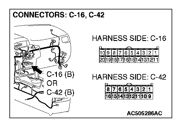
STEP 46. Check A/C-ECU connector C-42
CAUTION: The strand end of the twist wire should be within 10 cm (4 inches) from the connector.
Q: Is A/C-ECU connector C-42
YES: Go to Step 47.
NO: Repair the damaged parts.
STEP 47. Check the CAN_L line (communication line only) between joint connector (4) and A/C-ECU connector for short to ground. Measure the resistance at joint connector (4) C-101.
CAUTION:
- A digital multimeter should be used.
- The test wiring harness should be used.
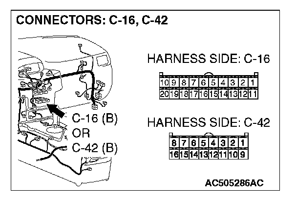
1. Disconnect joint connector (4) C-101 and A/C-ECU connector C-42
2. Turn the ignition switch to the "LOCK" (OFF) position.
CAUTION: Disconnect the negative battery terminal.
3. Disconnect the negative battery terminal.
4. Measure the resistance between joint connector (4) terminal 7 and body ground.
OK: 1 kohm or more
CAUTION: Strictly observe the specified wiring harness repair procedure.
Q: Does the resistance measure 1 kohm or more?
YES:
NO:
STEP 48. Check the CAN_L line (communication line including the SRS-ECU) between joint connector (4) and the SRS-ECU connector for short to ground. Measure the resistance at joint connector (4) C-101.
CAUTION:
- A digital multimeter should be used.
- The test wiring harness should be used.
1. Disconnect joint connector (4) C-101, and measure the resistance at the wiring harness side of joint connector (4) C-101.
2. Turn the ignition switch to the "LOCK" (OFF) position.
CAUTION: Disconnect the negative battery terminal.
3. Disconnect the negative battery terminal.
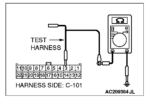
4. Measure the resistance between joint connector (4) terminal 3 and body ground.
OK: 1 kohm or more
Q: Does the resistance measure 1 kohm or more?
YES:
NO:
STEP 49. Check SRS-ECU connector C-26 for loose, corroded or damaged terminals, or terminals pushed back in the connector.

CAUTION: The strand end of the twist wire should be within 10 cm (4 inches) from the connector.
Q: Is SRS-ECU connector C-26 in good condition?
YES: Go to Step 50.
NO: Repair the damaged parts.