Assembly
Part 1 Of 2:

Part 2 Of 2:

ASSEMBLY
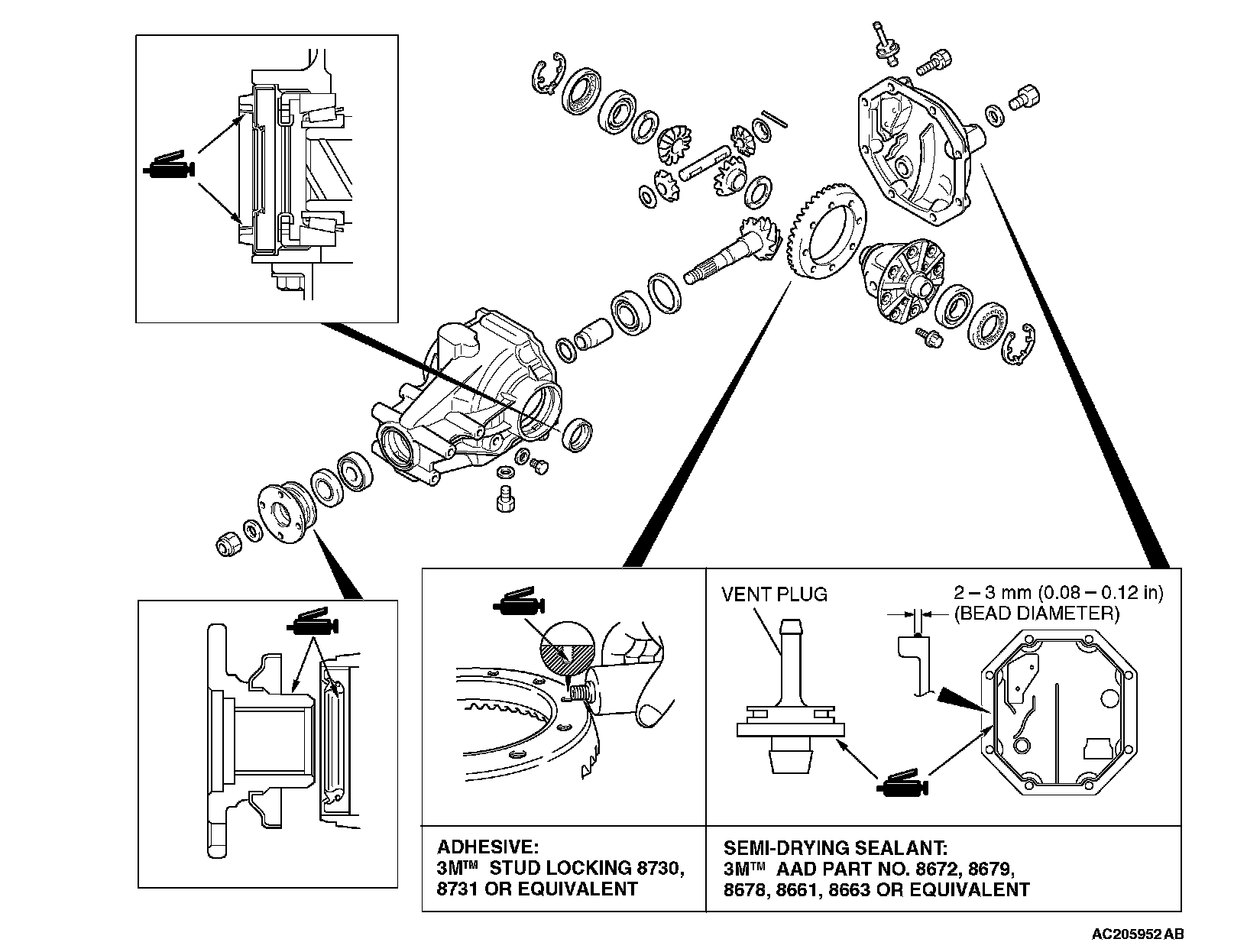
LUBRICATION AND ADHESIVE POINTS
ASSEMBLY SERVICE POINTS
]]A[[ OIL SEAL PRESS-FITTING
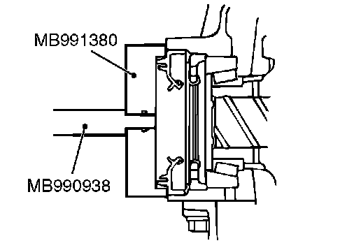
Use special tools MB990938 and MB991380 to press-fit the oil seal.
]]B[[ DRIVE PINION REAR BEARING OUTER RACE PRESS-FITTING
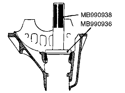
Use special tools MB990938 and MB990936 to press-fit the drive pinion rear bearing outer race.
]]C[[ DRIVE PINION FRONT BEARING OUTER RACE PRESS-FITTING
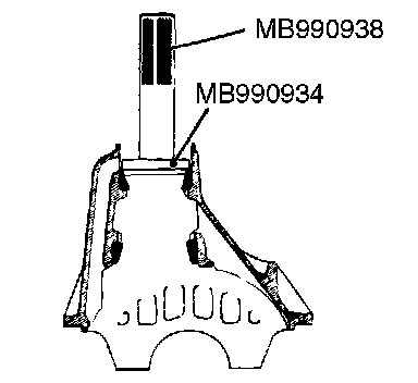
Use special tools MB990938 and MB990934 to press-fit the drive pinion front bearing outer race.
]]D[[ DRIVE PINION HEIGHT ADJUSTMENT
Adjust the drive pinion height by the procedures:
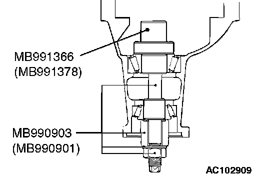
1. Apply multipurpose grease to the washer of special tool MB990903.
2. Install special tools MB990903 (MB990901) and MB991366 (MB991378), drive pinion front and rear bearing inner races to the differential carrier as shown in the illustration.
CAUTION: There should be no gear oil adhered to the bearing.
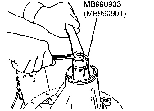
3. Tighten the nut of special tool MB990903 a little at a time, while measuring the turning torque of the drive pinion. Then confirm that the turning torque (without the drive pinion oil seal) is at the standard value.
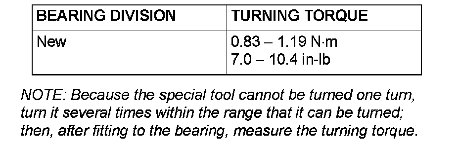
Standard value
NOTE: Because the special tool cannot be turned one turn, turn it several times within the range that it can be turned; then, after fitting to the bearing, measure the turning torque.
4. Clean thoroughly the side bearing seat of the differential carrier.
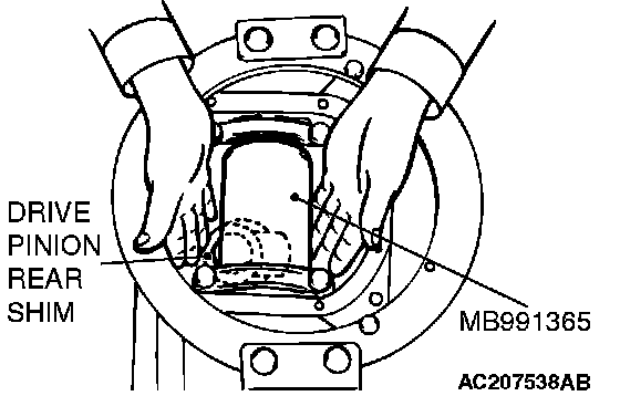
5. Place special tool MB991365 in the side bearing seat of the differential carrier, and then select a drive pinion rear shim of a thickness which corresponds to the gap between the special tools.
NOTE: When selecting the drive pinion rear shims, keep the number of shims to a minimum.
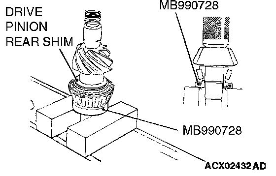
6. Fit the selected drive pinion rear shim(s) to the drive pinion, and press-fit the drive pinion rear bearing inner race by using special tool MB990728.
]]E[[ DRIVE PINION TURNING TORQUE ADJUSTMENT/OIL SEAL INSTALLATION
Adjust the drive pinion turning torque by the procedures:
1. Insert the drive pinion into the differential carrier, and then install the parts in sequence from the carrier rear side: drive pinion spacer, drive pinion front shim, drive pinion front bearing inner race and companion flange.
NOTE: Do not install the oil seal.
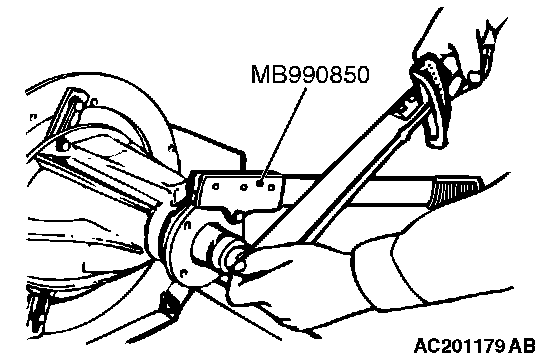
2. Tighten the companion flange self-locking nut to the specified torque while holding the companion flange with special tool MB990850.
Tightening torque: 186 ± 29 Nm (137 ± 21 ft. lbs.)
CAUTION: There should be no gear oil adhered to the bearing.
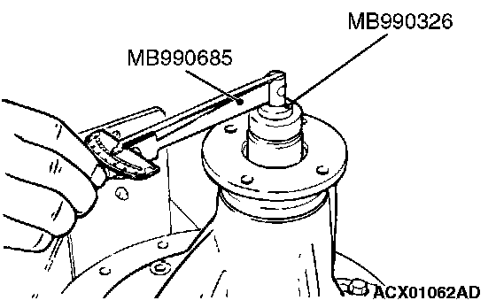
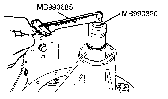
3. Use special tools MB990685 and MB990326 to measure the drive pinion turning torque (without the drive pinion oil seal).

Standard value
4. If the drive pinion turning torque is not within the standard value, adjust the turning torque by replacing the drive pinion front shim(s) or the drive pinion spacer.
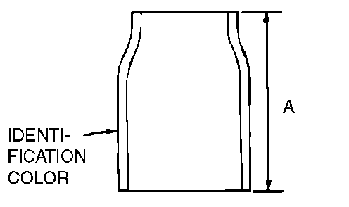
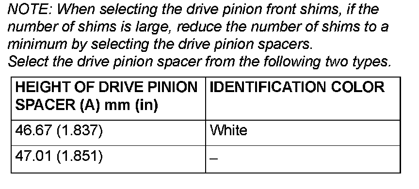
NOTE: When selecting the drive pinion front shims, if the number of shims is large, reduce the number of shims to a minimum by selecting the drive pinion spacers. Select the drive pinion spacer from the two types.
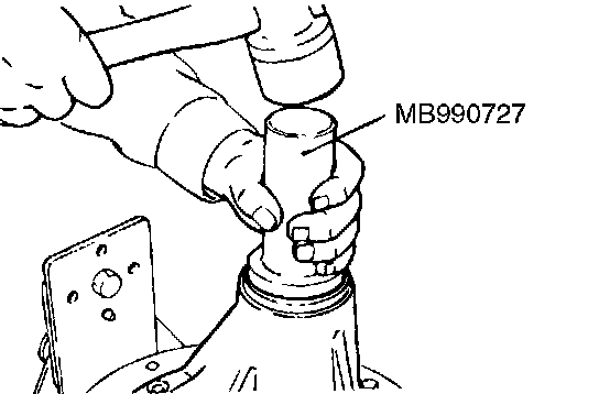
5. Remove the companion flange and drive pinion again. Then insert the drive pinion front bearing inner race into the differential carrier. Use special tool MB990727 to press-fit the drive pinion oil seal.
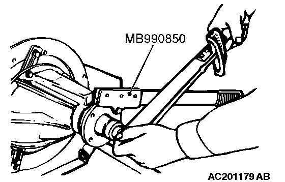
6. Install the drive pinion assembly and companion flange with the mating marks properly aligned. Tighten the companion flange self-locking nut to the specified torque while holding the companion flange with special tool MB990850.
Tightening torque: 186 ± 29 Nm (137 ± 21 ft. lbs.)
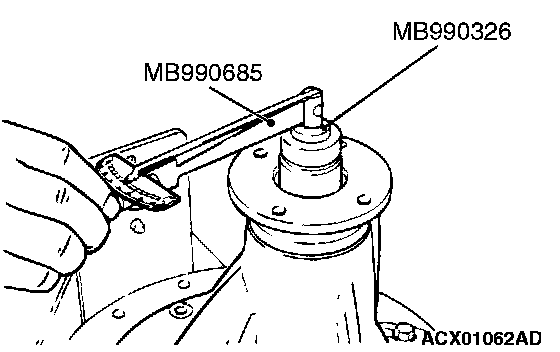
7. Use special tools MB990685 and MB990326 to measure the drive pinion turning torque (with drive pinion oil seal) to verify that the drive pinion turning torque complies with the standard value.
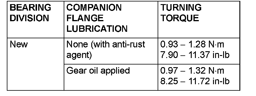
Standard value
8. If the turning torque is not within the standard value, check the tightening torque of the companion flange self-locking nut, and the installation of the oil seal.
]]F[[ DIFFERENTIAL GEAR BACKLASH ADJUSTMENT
Adjust the differential gear backlash by the procedure:
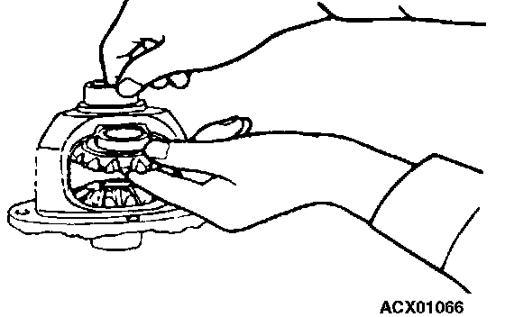
1. Assemble the side gears, side gear spacers, pinion gears, and pinion washers into the differential case.
2. Temporarily install the pinion shaft.
NOTE: Do not assemble the lock pin yet.
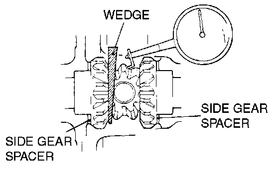
3. Insert a wedge between the side gear and the pinion shaft to lock the side gear.
4. While locking the side gear with the wedge, measure the differential gear backlash with a dial indicator on the pinion gear. Measure by the same procedure for the other pinion gear.
Standard value: 0.01 - 0.250 mm (0.0004 - 0.0098 inch)
Limit: 0.2 mm (0.01 inch)
5. If the backlash exceeds the limit value, adjust it by replacing the side gear spacers.
6. If adjustment is not possible, replace the side gears and pinion gears as a set.
7. Check that the backlash is within the limit value and that the differential gear turns smoothly.
]]G[[ LOCK PIN INSTALLATION
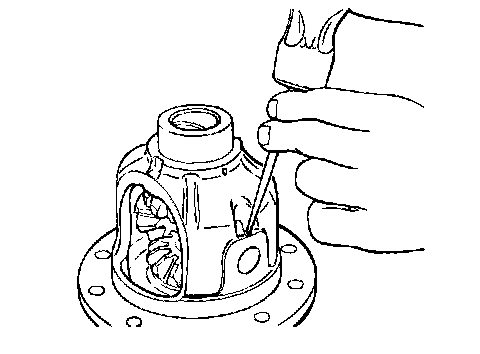
1. Align the pinion shaft lock pin hole with the differential case lock pin hole, and drive in the lock pin.
2. Stake the lock pin with a punch on both sides.
]]H[[ DRIVE GEAR INSTALLATION
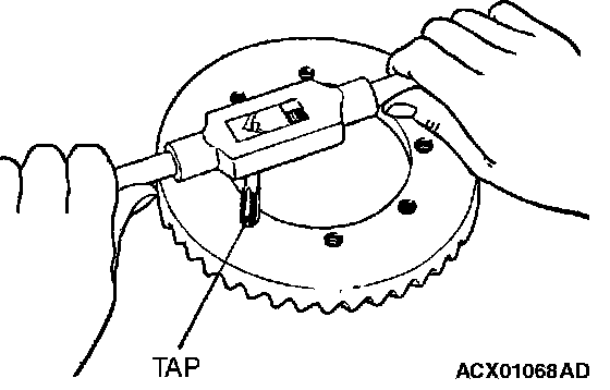
1. Clean the drive gear attaching bolts.
2. Remove the adhesive adhered to the threaded holes of the drive gear by turning the tap (M10 x 1.25). Clean the threaded holes by applying compressed air.
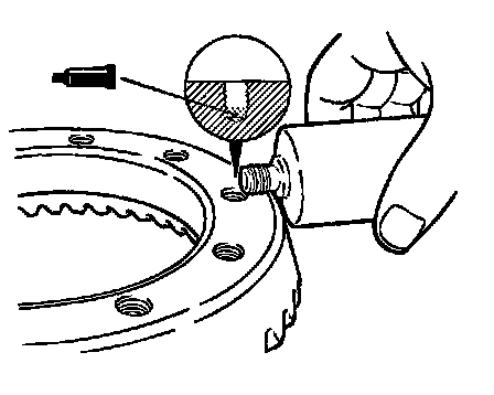
3. Apply 3M(TM) stud locking 8730, 8731 or equivalent to the threaded holes of the drive gear.
4. Install the drive gear onto the differential case with the mating marks properly aligned. Tighten the drive gear attaching bolts to the specified torque in a diagonal sequence.
Tightening torque: 84 ± 4 Nm (62 ± 3 ft. lbs.)
]]I[[ DIFFERENTIAL SIDE BEARING INNER RACE INSTALLATION
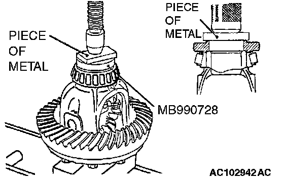
Use special tool MB990728 to press-fit the differential side bearing inner races into the differential case.
]]J[[ DIFFERENTIAL SIDE BEARING NUT INSTALLATION/SNAP RING INSTALLATION/FINAL DRIVE GEAR BACKLASH ADJUSTMENT
Adjust the final drive gear backlash by the procedure:
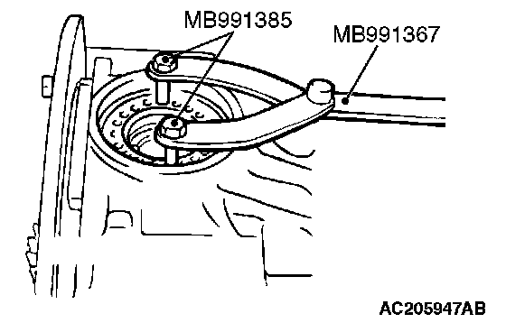
1. Using special tools MB991367 and MB991385, temporarily tighten the side bearing nut to just before preloading of the side bearing.
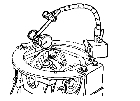
2. Measure the final drive gear backlash at four points or more on the circumference of the drive gear.
Standard value: 0.11 - 0.16 mm (0.004 - 0.006 inch)
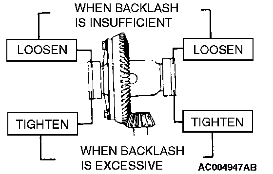
3. Using special tools MB991367, MB991385, adjust the backlash to standard value by moving the side bearing nut as shown.
NOTE: First loosen the side bearing nut then tighten the side bearing nut the same amount as when it was loosened.
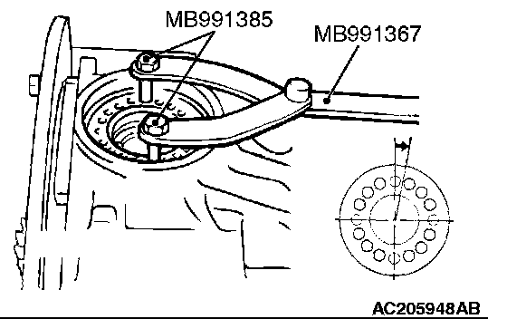
4. Using special tools MB991367 and MB991385, apply the preload, turn down both right and left side bearing nuts on half the distance between centers of two neighboring holes.
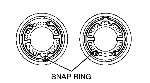
5. Fit the snap ring at either position shown to lock the side bearing nut.
6. Check the final drive gear tooth contact. If poor contact is evident, make adjustment.
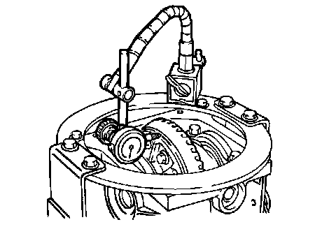
7. Measure the drive gear runout.
Limit: 0.05 mm (0.002 inch)
8. If drive gear runout exceeds the limit, remove the differential case and then the drive gears, moving them to different positions and reinstall them.
9. If adjustment is not possible, replace the differential case or drive gear and drive pinion as a set.