Inspection Procedure 26
INSPECTION PROCEDURE 26: Fans (Radiator Fan, A/C Condenser Fan) Are InoperativeRadiator Fan, A/C Condenser Fan Circuit:
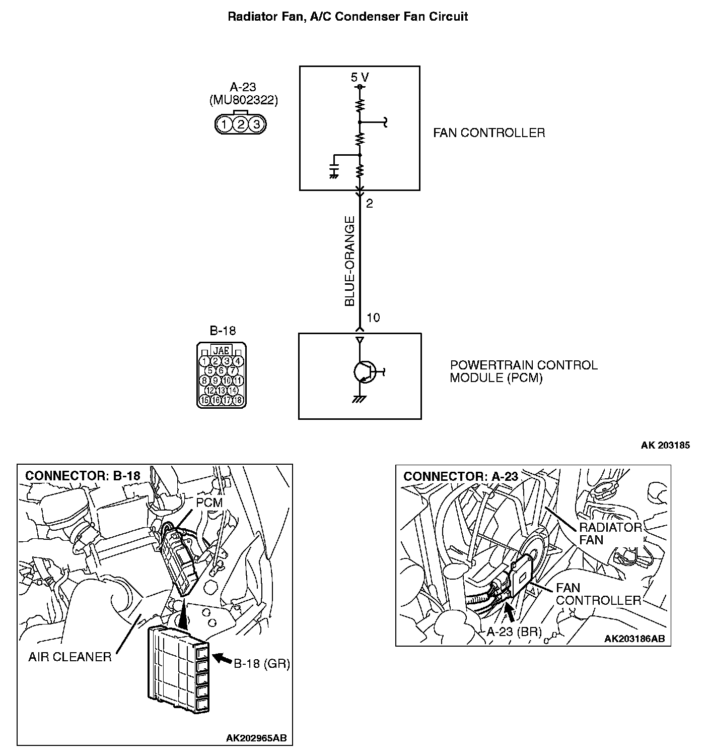
CIRCUIT OPERATION
- The PCM sends a duty signal to the fan controller according to engine coolant temperature, vehicle speed, and the condition of the A/C switch. (The closer the average voltage at the terminal comes to 5 volts, the higher the fan speed becomes.)
TROUBLESHOOTING HINTS (The most likely causes for this code to be set are: )
- Malfunction of the fan motor relay.
- Malfunction of the fan motor.
- Malfunction of the fan controller.
- Improper connector contact, open or short-circuited harness wire.
- PCM failed.
DIAGNOSIS
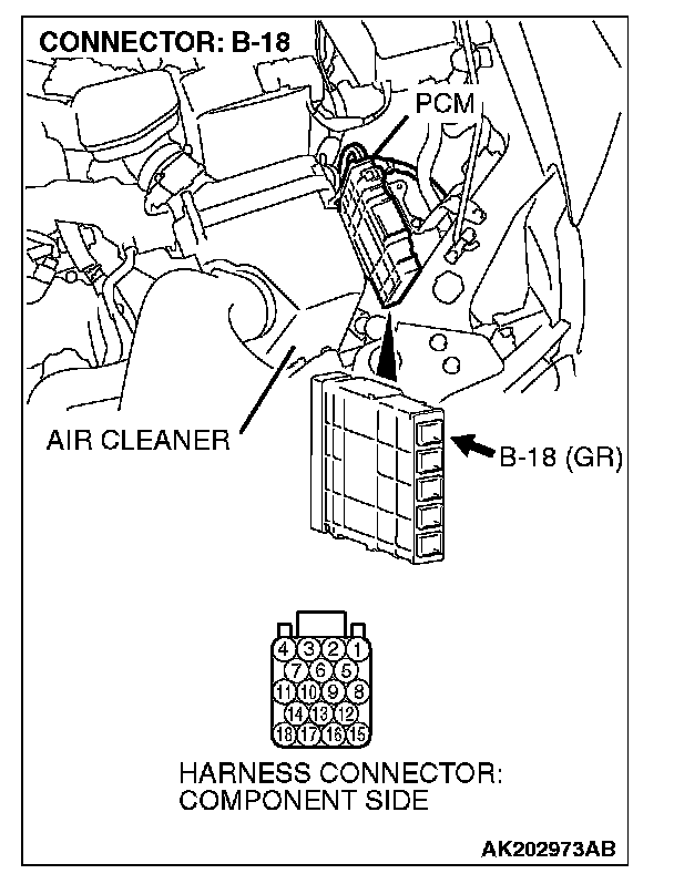
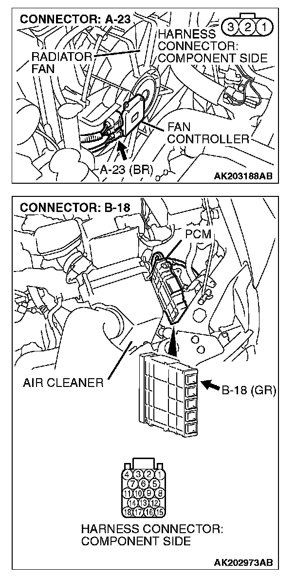
STEP 1. Check harness connector B-18 at PCM for damage.
Q: Is the harness connector in good condition?
YES : Go to Step 2.
NO : Repair or replace it. Refer to General (Electrical), Harness Connector Inspection. Then confirm that the malfunction symptom is eliminated.
STEP 2. Measure the output voltage at PCM harness side connector B-18.
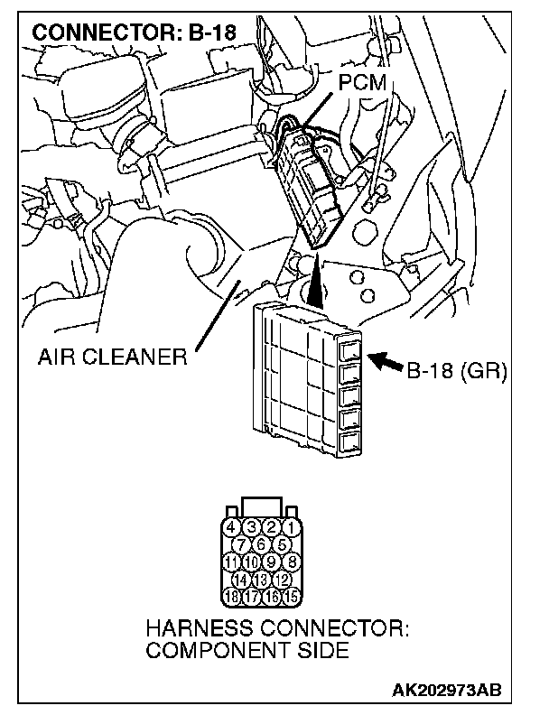
1. Disconnect the B-18 and measure at the harness side.
2. Turn the ignition switch to the "ON" position.
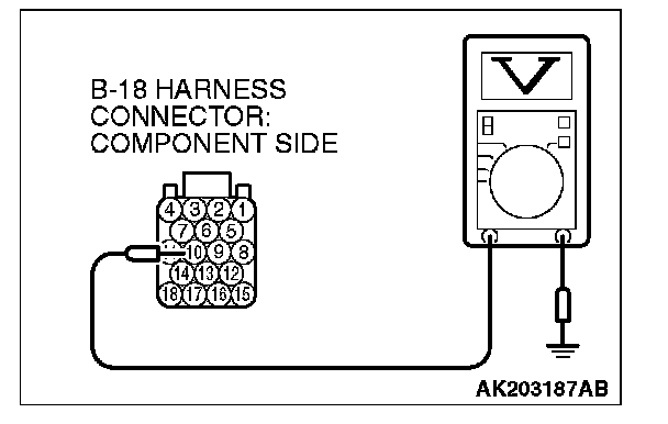
3. Measure the voltage between terminal No. 10 and ground.
- Voltage should be between 4.9 and 5.1 volts. (Fan rotates at high speed.)
4. Connect a jumper cable between terminal No. 10 and ground.
- The fan should stop.
5. Turn the ignition switch to the "LOCK" (OFF) position.
Q: Are the measured voltage and fan condition normal?
YES : Replace the PCM. When the PCM is replaced, register the encrypted code. Refer to Chassis Electrical, Encrypted Code Registration Criteria Table. Ignition Switch - Then confirm that the malfunction symptom is eliminated.
NO : Go to Step 3.
STEP 3. Check for open circuit and short circuit to ground and harness damage between fan controller A-23 (terminal No. 2) and PCM connector B-18 (terminal No. 10).
Q: Is the harness wire in good condition?
YES : Refer to Engine Cooling Diagnosis -Symptom Chart.
NO : Repair it. Then confirm that the malfunction symptom is eliminated.