Intake Manifold: Service and Repair
MANIFOLD-INTAKEREMOVAL
1. Bleed the fuel system.
2. Disconnect the negative cable from battery.
3. Remove the resonator assembly and air inlet hose.
4. Drain the cooling system below coolant temperature sensor level.
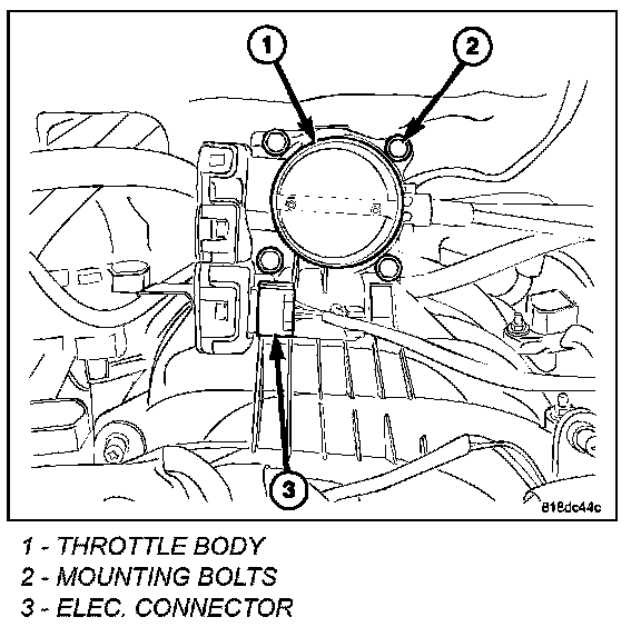
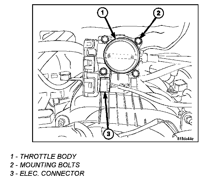
5. Disconnect the electronic throttle control (ETC) connector (3).
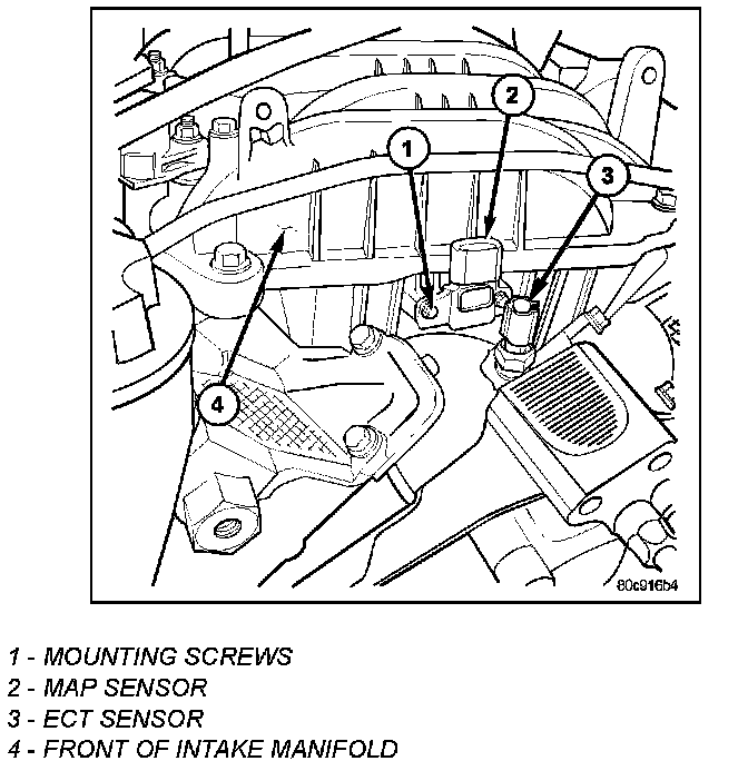
6. Disconnect electrical connectors for the following components:
^ Coolant Temperature Sensor
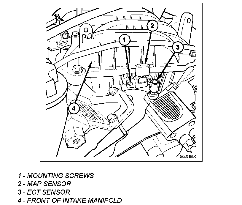
^ Manifold Absolute Pressure (MAP) Sensor (2)

7. Disconnect vapor purge hose, brake booster hose, and positive crankcase ventilation (PCV) hose.
8. Disconnect and remove ignition coil towers.
9. Remove the top oil dipstick tube retaining bolt.
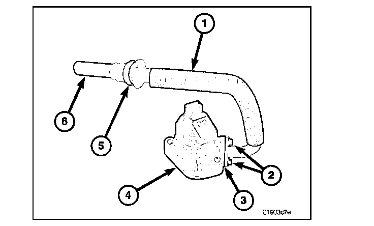
10. Remove the EGR tube (1).
11. Remove fuel rail.
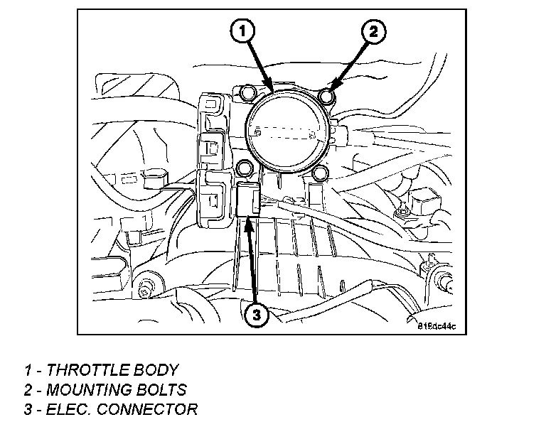
12. Remove throttle body assembly (1).
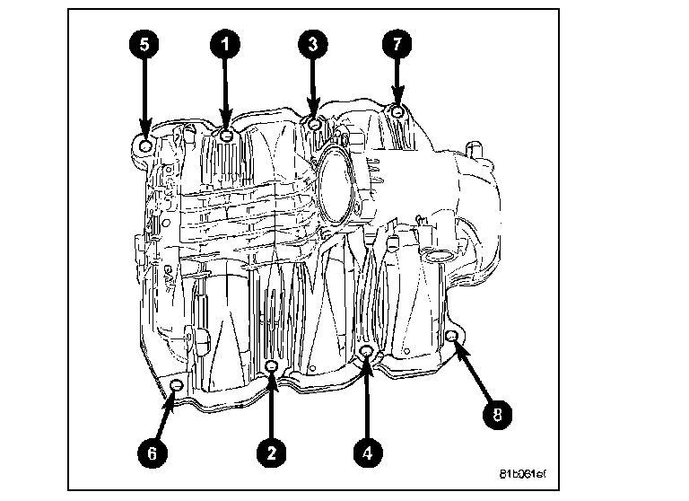
13. Remove the intake manifold retaining fasteners in reverse order of tightening sequence.
14. Remove the intake manifold.
INSTALLATION

1. Install the intake manifold seals.
2. Install the intake manifold.
3. Install the intake manifold retaining bolts and tighten in sequence shown to 12 Nm (105 in. lbs.).
CAUTION
Proper torque of the throttle body is critical to normal operation. If the throttle body is over-torqued, damage to the throttle body can occur resulting in throttle plate malfunction.
4. Install the throttle body-to-intake manifold O-ring.
5. Install the throttle body (1) to intake manifold.
6. Install the four mounting bolts (2). Tighten bolts to 7 Nm (60 in. lbs.).
7. Install electrical connector (3).
8. Install the fuel rail.
9. Install the EGR tube (1).
10. Install ignition coil towers.
11. Connect electrical connectors for the following components:
^ Manifold Absolute Pressure (MAP) Sensor (2)
^ Coolant Temperature (CTS) Sensor
^ Ignition coil towers
12. Install top oil dipstick tube retaining bolt.
13. Connect Vapor purge hose, Brake booster hose, Positive crankcase ventilation (PCV) hose.
14. Fill the cooling system.
15. Install the resonator assembly and air inlet hose.
16. Connect the negative cable to battery.
17. Using the scan tool, perform the ETC Relearn function.