Heating and Air Conditioning: Description and Operation
HVAC - SERVICE INFORMATIONDESCRIPTION
A manual temperature control (MTC) single zone type heating-A/C system is standard equipment on this vehicle.
To maintain the performance level of the heating, ventilation and air conditioning (HVAC) system, the engine cooling system must be properly maintained. The use of a bug screen is not recommended. Any obstructions in front of the radiator or A/C condenser will reduce the performance of the A/C and engine cooling systems.
The engine cooling system includes the radiator, thermostat, radiator hoses and the engine coolant pump. Refer to Cooling before opening or attempting any service to the engine cooling system.
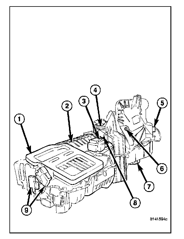
All vehicles are equipped with a common heater, ventilation and air conditioning (HVAC) housing (1). The heating-A/C system combines A/C, heating, and ventilating capabilities in a single HVAC housing mounted within the passenger compartment behind the instrument panel. The HVAC housing includes:
- Heater core (2)
- Blend-air doors and actuator (3)
- A/C evaporator (4)
- Blower motor resistor (5)
- Recirculation-air door and actuator (6)
- Blower motor (7)
- Evaporator temperature sensor (8)
- Mode-air doors and actuators (9)
Based upon the mode selected, conditioned air can exit the HVAC housing through one or a combination of the three main housing outlets: defrost, panel or floor. The defrost and panel outlets are located on the top of the HVAC housing and the floor outlet is located on the bottom of the HVAC housing. Once the conditioned air exits the HVAC housing, it is further directed through molded plastic ducts to the outlets within the vehicle interior. These outlets and their locations are as follows:
Defroster Outlet - A single large defroster outlet is located in the center of the instrument panel top cover, near the base of the windshield.
Side Window Demister Outlets - There are two side window demister outlets, one is located at each outboard end of the instrument panel face near the A-pillars.
Panel Outlets - There are four panel outlets in the instrument panel, one located near each out-board end of the instrument panel facing the rear of the vehicle and two located at the top of the instrument panel center bezel.
Floor Outlets - There are two floor outlets, one located above each side of the floor panel center tunnel near the dash panel.
OPERATION
The heating-A/C system used in this vehicle is a single zone, blend-air type system. In this blend-air heating-A/C system, two blend-air doors control the amount of conditioned air that is allowed to flow through, or around the heater core. The temperature control determines the discharge air temperature by operating the blend-air doors. This allows an almost immediate control of the output air temperature of the system.
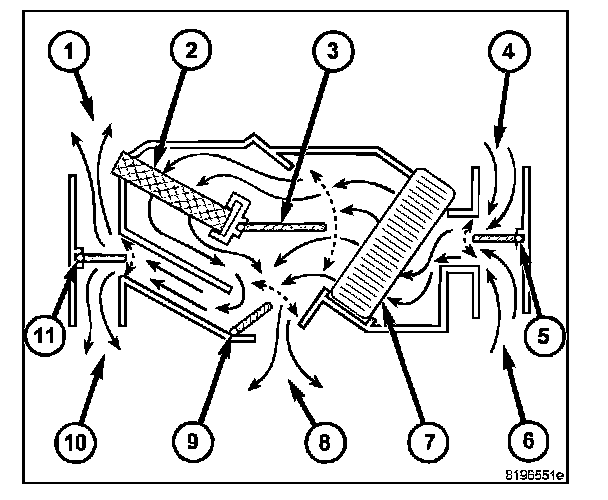
NOTE: Typical blend-air type HVAC system shown. The heating-A/C system pulls outside (ambient) air through the fresh air intake (4) located at the cowl panel at the base of the windshield and into the air inlet housing above the heating, ventilation and air conditioning (HVAC) housing and through the A/C evaporator (7). Air flow is then directed either through or around the heater core (2). This is done by adjusting the position of the blend-air doors (3) with the temperature control located on the A/C-heater control in the instrument panel. Air flow is then directed out the floor outlet (8), instrument panel outlet (10) or the defroster outlet (1) in various combinations by adjusting the position of the mode-air doors (9 and 11) using the mode control located on the A/ C-heater control. The temperature and mode control uses electrical actuators to operate the air doors. The velocity of the air flow out of the outlets can be adjusted with the blower speed control located on the A/C-heater control.
The fresh air intake can be shut off by pressing the Recirculation button on the A/C-heater control. This will operate the electrically actuated recirculation-air door (5), which closes off the fresh air intake. With the fresh air intake closed, the conditioned air within the vehicle is pulled back into the HVAC housing through the recirculation air intake (6) located within the passenger compartment.
The A/C compressor can be engaged by pressing the A/C (snowflake) button on the A/C-heater control. It will automatically engage when the mode control is set in any Mix to Defrost position. This will remove heat and humidity from the air before it is directed through or around the heater core. The mode control on the A/C-heater control is used to direct the conditioned air to the selected system outlets.
The defroster outlet receives airflow from the HVAC housing through the molded plastic defroster duct, which connects to the HVAC housing defroster outlet. The airflow from the defroster outlet is directed by fixed vanes in the defroster outlet grille and cannot be adjusted. The defroster outlet grille is serviceable from the instrument panel.
The side window demister outlets receive airflow from the HVAC housing through the molded plastic demister ducts. The demisters direct air from the HVAC housing through the outlets located on the top corners of the instrument panel. The demisters operate when the mode control is positioned in the bi-level, floor, floor-defrost and defrost settings. The air-flow from the side window demister outlets is directed by fixed vanes in the demister outlet grilles and cannot be adjusted. The demister outlet grilles are only serviced with the instrument panel outlets. The instrument panel outlets receive airflow from the HVAC housing through a molded plastic center distribution duct, center panel duct and two end panel ducts. The two end panel ducts direct airflow to the left and right instrument panel outlets, while the center panel duct directs airflow to the two center panel outlets. Each of these outlets can be individually adjusted to direct the flow of air.
The floor outlets receive airflow from the HVAC housing through the floor distribution duct. The front floor outlets are integral to the molded plastic floor distribution duct, which is secured to the bottom of the HVAC housing. The floor outlets cannot be adjusted.
NOTE: It is important to keep the air intake opening clear of debris. Leaf particles and other debris that is small enough to pass through the cowl opening screen can accumulate within the HVAC housing. The closed, warm, damp and dark environment created within the housing is ideal for the growth of certain molds, mildews and other fungi. Any accumulation of decaying plant matter provides an additional food source for fungal spores, which enter the housing with the fresh intake-air. Excess debris, as well as objectionable odors created by decaying plant matter and growing fungi can be discharged into the passenger compartment during heater-A/C operation if the air intake opening is not kept clear of debris.
This A/C system uses an A/C orifice tube to meter the flow of refrigerant to the A/C evaporator. The A/C evaporator cools and dehumidifies the incoming air prior to blending it with the heated air. To maintain minimum evaporator temperatures and prevent evaporator freezing, an evaporator temperature sensor is used. The sensor is located downstream of the A/C evaporator and supplies an evaporator temperature signal to the A/C-heater control. The A/C-heater control broadcasts the A/C request on the controller area network (CAN) B bus, where it is read and processed by the front control module (FCM), which in turn broadcasts it on the CAN C bus, where it is read and processed by the powertrain control module (PCM) which cycles the A/C clutch relay as necessary.