Part 1
DISASSEMBLY SERVICE POINTCAUTION: Do not disassemble parts other than specified in this manual.
1. Remove the transfer from the transaxle. [W1CJA]
2. Remove the RR roll stopper bracket and FR roll stopper bracket from the transaxle.
3. Remove the harness bracket from the transaxle.
4. Remove the oil filler tube and oil level gage from the transaxle.
5. Remove the control cable bracket and breather hose from the transaxle.
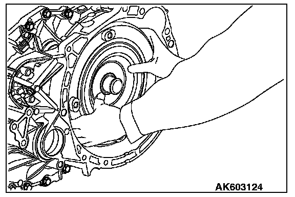
6. Remove the torque converter from the transaxle.
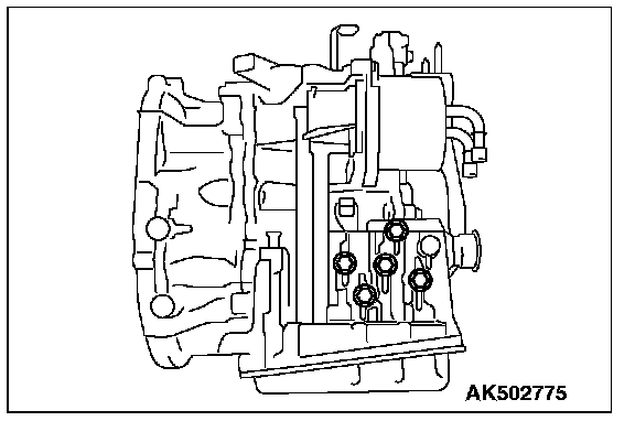
7. Remove the plug from the transaxle case.
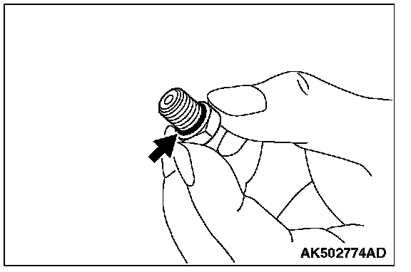
8. Remove the O-ring from the plug.
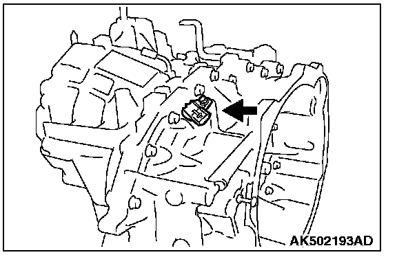
9. Remove the secondary pulley speed sensor from the converter housing, and detach the O-ring from the sensor.
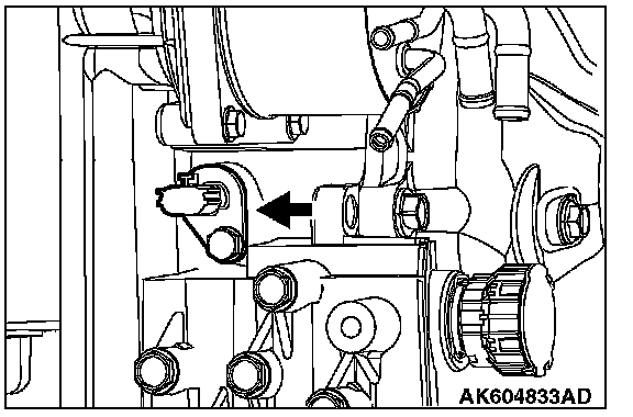
10. Remove the primary pulley speed sensor from the transaxle case, and detach the O-ring from the sensor.
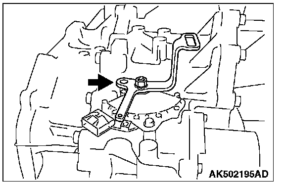
11. Remove the shift lever from the manual shaft.
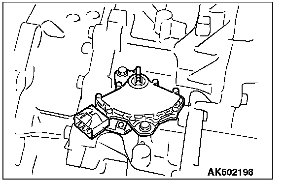
12. Remove the inhibitor switch from the transaxle.
CAUTION: Be careful not to cause damage to the terminal body.
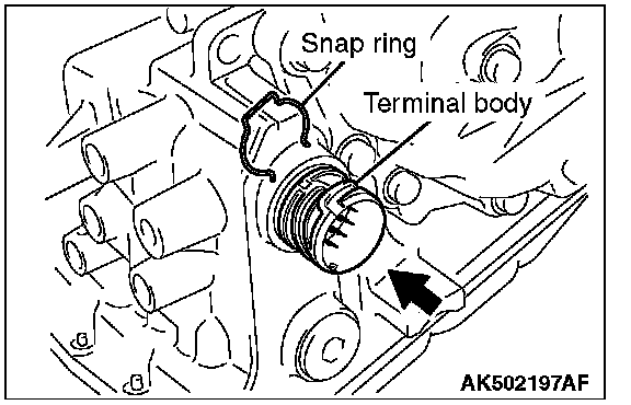
13. Remove the snap ring from the terminal body, and press the terminal body into the transaxle case.
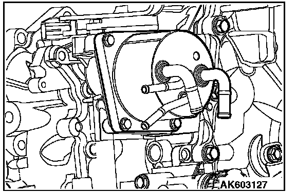
14. Remove the CVT fluid cooler from the transaxle case, and detach the O-ring from the cooler.
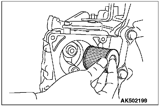
15. Remove the CVT fluid filter from the transaxle case.
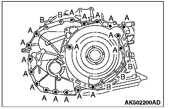
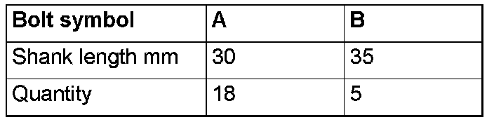
16. Remove the fastening bolts of converter housing.
CAUTION: Be careful because adjusting shim of the drive sprocket may depart.
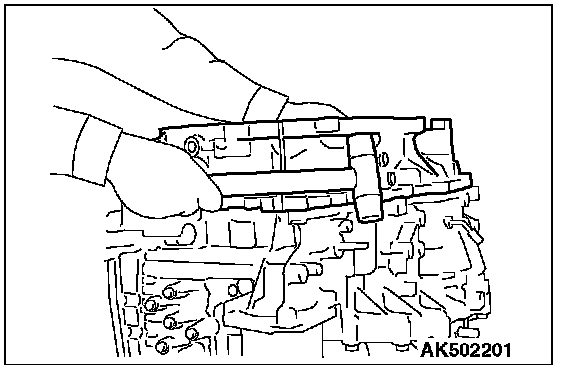
17. Remove the converter housing by tapping with a plastic hammer etc.
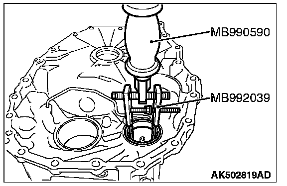
18. Using the special tools MB990590 and MB992039, remove the outer race of reduction gear bearing from the converter housing.
19. Using cylinder gage etc., measure the mounting bore diameter of reduction gear bearing outer race at the converter housing side; if the standard value is not satisfied, then replace the converter housing.
Standard value: diameter 61.949 - 61.979 mm (diameter 2.4389 - 2.4401 in)
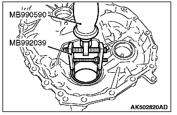
20. Using the special tools MB990590 and MB992039, remove the outer race of differential side bearing from the converter housing.
21. Using cylinder gage etc., measure the mounting bore diameter of differential side bearing outer race at the converter housing side; if the standard value is not satisfied, then replace the converter housing.
Standard value
F1CJA: diameter 67.949 - 67.979 mm (diameter 2.6752 - 2.6763 in)
W1CJA: diameter 84.941 - 84.976 mm (diameter 3.3441 - 3.3455 in)
CAUTION: When removing the oil seal, be careful not to cause damage to the converter housing.
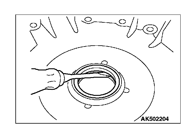
22. Using a flat blade screwdriver etc., remove the converter housing oil seal from the housing.
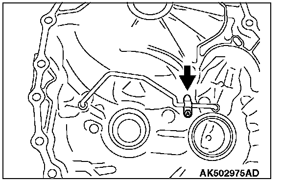
23. Remove the clip.
CAUTION: When removing the pipe, be careful not to bend it.
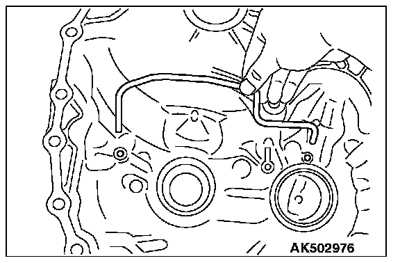
24. Remove the pipe from the converter housing.
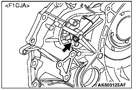
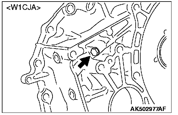
25. Remove the plug from the converter housing.
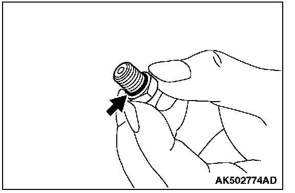
26. Remove the O-ring from the plug.
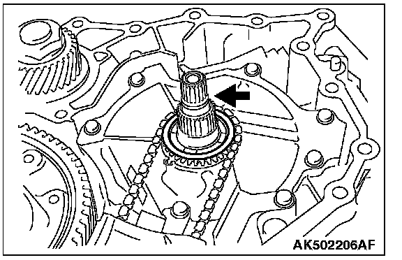
27. Remove the O-ring from the input shaft.
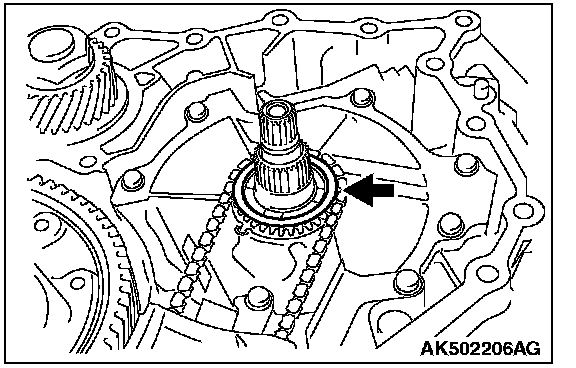
28. Remove the adjusting shim from the drive sprocket.
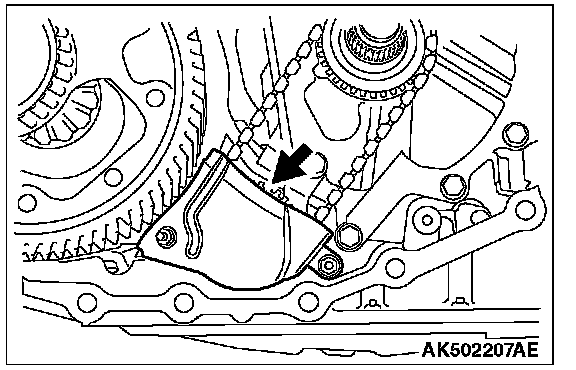
29. Remove the baffle plate.
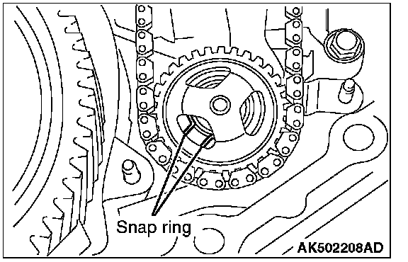
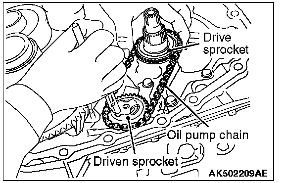
30. Expand the snap ring, and remove the driven sprocket, oil pump chain, and drive sprocket.
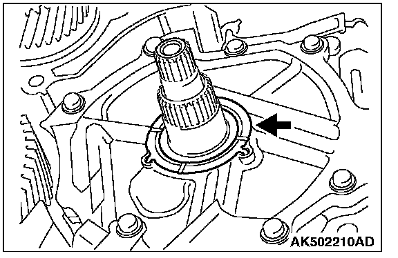
31. Remove the thrust washer from the oil pump cover.
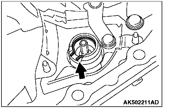
32. Remove the snap ring from the oil pump.
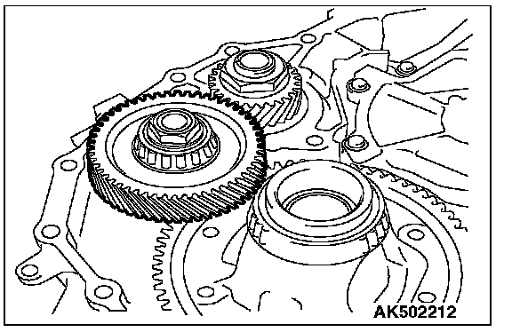
33. Remove the reduction gear assembly from the transaxle case.
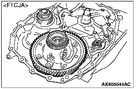
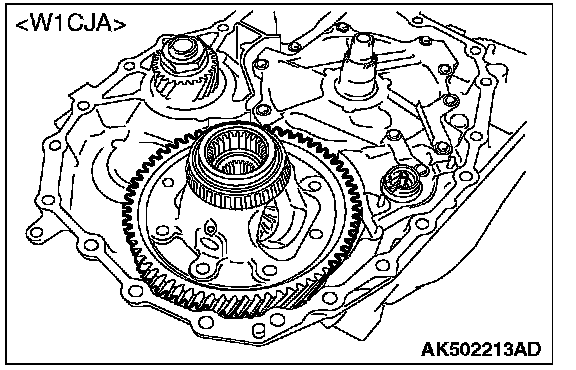
34. Remove the differential assembly from the transaxle case.
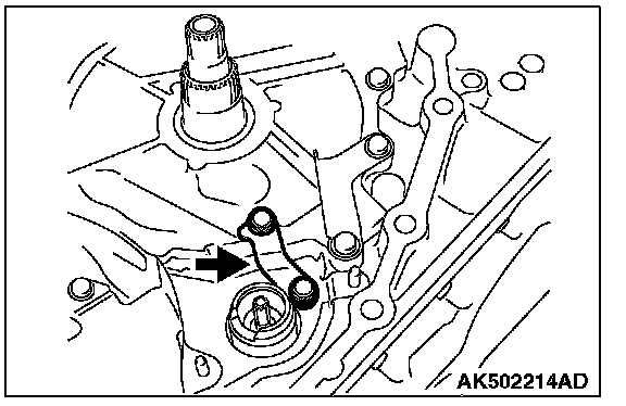
35. Remove the bracket.
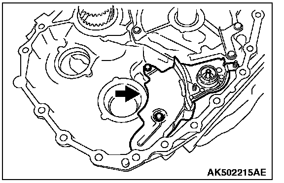
CAUTION: Be careful. Do not use to much air pressure as this may cause the reverse brake piston be stuck.
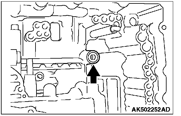
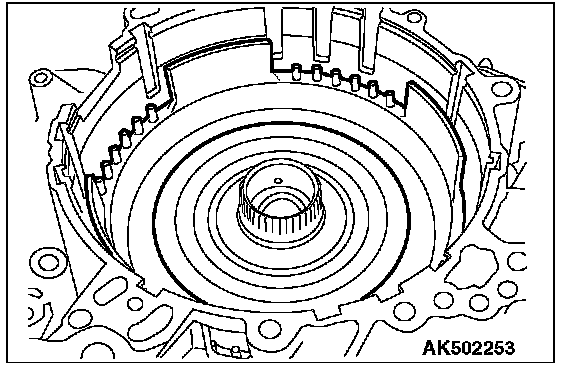
72. Feed the air in the oil hole shown in the diagram, and remove the reverse brake piston from the transaxle case.