Part 2
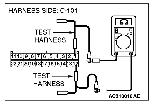
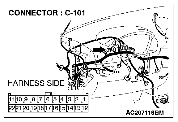
STEP 22. Check the CAN_L and H lines (communication lines only) between joint connector (4) and the TPMS receiver for a short circuit. Measure the resistance at joint connector (4) C-101.CAUTION:
- A digital multimeter should be used.
- The test wiring harness should be used.
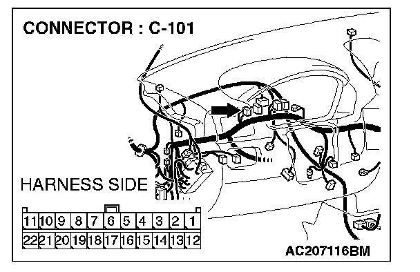
1. Disconnect joint connector (4) C-101 and TPMS receiver connector C-118, and measure the resistance at the wiring harness side of joint connector (4) C-101.
2. Turn the ignition switch to the "LOCK" (OFF) position.
CAUTION: Disconnect the negative battery terminal.
3. Disconnect the negative battery terminal.
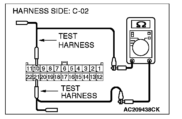
4. Measure the resistance between joint connector (4) terminals 10 and 21.
OK: 1 kohms or more
CAUTION: Strictly observe the specified wiring harness repair procedure.
Q: Does the resistance measure 1 kohms or more?
YES : If the resistance measures 1 kohms or more, go to Step 23.
NO : If the resistance measures less than 1 kohms, repair the wiring harness between joint connector (3) and the TPMS receiver connector.
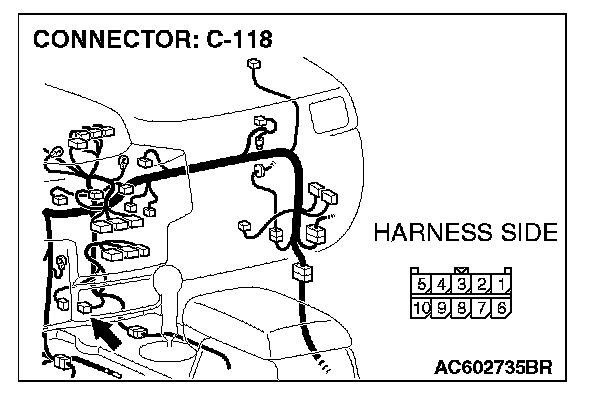
STEP 23. Check the TPMS receiver for short circuit. Measure the resistance at TPMS receiver connector C-118.
CAUTION: A digital multimeter should be used.
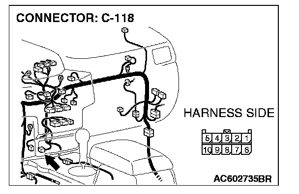
1. Disconnect TPMS receiver connector C-118, and measure the resistance at the component side of TPMS receiver connector C-118.
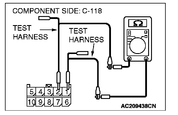
2. Measure the resistance between TPMS receiver connector terminals 1 and 2.
OK: 1 kohms or more
Q: Does the resistance measure 1 kohms or more?
YES : If the resistance measures 1 kohms or more, diagnose CAN bus lines thoroughly by referring to Diagnostic Item 9. Diagnostic Item 9
NO : If the resistance measures less than 1 kohms, replace the TPMS receiver.
STEP 24. Check the CAN_L and H lines (communication lines including the G and yaw rate sensor) between joint connector (4) and the G and yaw rate sensor for short circuit. Measure the resistance at joint connector (4) C-101.
CAUTION:
- A digital multimeter should be used.
- The test wiring harness should be used.
1. Disconnect joint connector (4) C-101, and measure the resistance at the wiring harness side of joint connector (4) C-101.
2. Turn the ignition switch to the "LOCK" (OFF) position.
CAUTION: Disconnect the negative battery terminal.
3. Disconnect the negative battery terminal.
4. Measure the resistance between joint connector (4) terminals 1 and 12.
OK: 1 kohms or more
Q: Does the resistance measure 1 kohms or more?
YES : [The resistance measures 1 kohms or more] Go to Step 29.
NO : [The resistance measures less than 1 kohms] Go to Step 25.
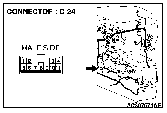
STEP 25. Check G and yaw rate sensor connector C-36 and intermediate connector C-24 for loose, corroded or damaged terminals, or terminals pushed back in the connector.
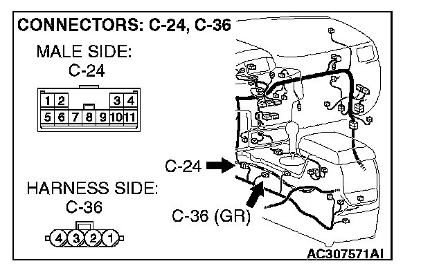
CAUTION: The strand end of the twist wire should be within 10 cm (4 inches) from the connector.
Q: Are G and yaw rate sensor connector C-36 and intermediate connector C-24 in good condition?
YES : Go to Step 26.
NO : Repair the damaged parts.
STEP 26. Check the CAN_L and H lines (communication lines only) between intermediate connector and the G and yaw rate sensor for short circuit. Measure the resistance at intermediate connector C-24.
CAUTION:
- A digital multimeter should be used.
- The test wiring harness should be used.
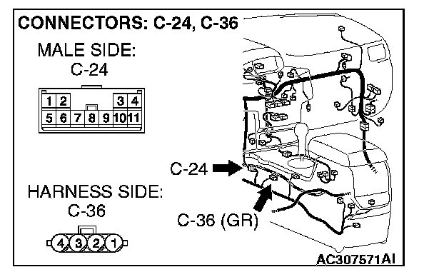
1. Disconnect intermediate connector C-24 and G and yaw rate sensor connector C-36, and measure the resistance at the wiring harness side of intermediate connector C-24.
2. Turn the ignition switch to the "LOCK" (OFF) position.
CAUTION: Disconnect the negative battery terminal.
3. Disconnect the negative battery terminal.
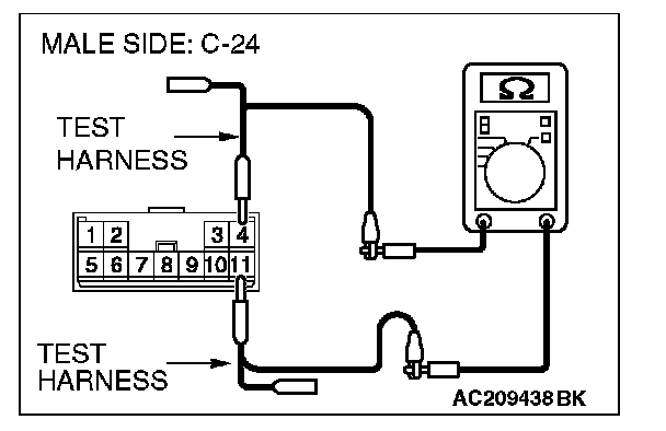
4. Measure the resistance between intermediate connector terminals 4 and 11.
OK: 1 kohms or more
CAUTION: Strictly observe the specified wiring harness repair procedure.
Q: Does the resistance measure 1 kohms or more?
YES : [The resistance measures 1 kohms or more] Go to Step 27.
NO : [The resistance measures less than 1 kohms] Repair the wiring harness between intermediate connector C-24 and G and yaw rate sensor connector.
STEP 27. Check the G and yaw rate sensor for short circuit. Measure the resistance at G and yaw rate sensor connector C-36.
CAUTION: A digital multimeter should be used.
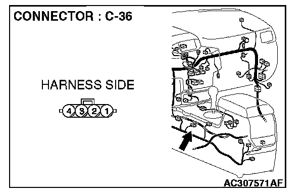
1. Disconnect G and yaw rate sensor connector C-36, and measure the resistance at the equipment side of G and yaw rate sensor connector C-36.
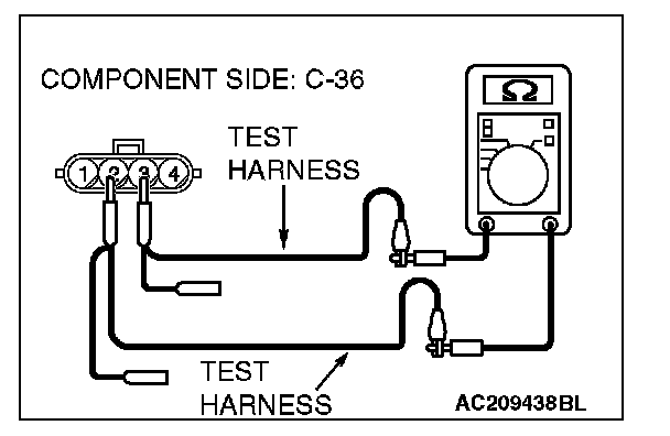
2. Measure the resistance between the G and yaw rate sensor connector terminals 2 and 3.
OK: 1 kohms or more
Q: Does the resistance measure 1 kohms or more?
YES : [The resistance measures 1 kohms or more] Go to Step 28.
NO : [The resistance measures lower than 1 kohms] Replace the g and yaw rate sensor.
STEP 28. Check the CAN_L and H lines (communication lines only) between joint connector (4) and the intermediate connector for short circuit. Measure the resistance at joint connector (4) C-101.
CAUTION:
- A digital multimeter should be used.
- The test wiring harness should be used.
1. Disconnect intermediate connector C-24 and joint connector (4) C-101, and measure the resistance at the wiring harness side of joint connector (4) C-101.
2. Turn the ignition switch to the "LOCK" (OFF) position.
CAUTION: Disconnect the negative battery terminal.
3. Disconnect the negative battery terminal.
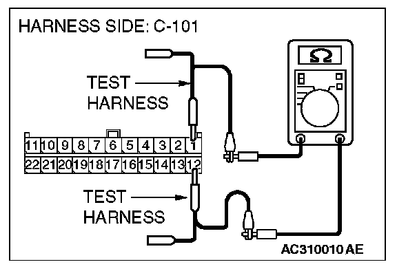
4. Measure the resistance between joint connector (4) terminals 1 and 12.
OK: 1 kohms or more
CAUTION: Strictly observe the specified wiring harness repair procedure.
Q: Does the resistance measure 1 kohms or more?
YES : [The resistance measures 1 kohms or more] Diagnose CAN bus lines thoroughly by referring to Diagnostic Item 9. Diagnostic Item 9
NO : [The resistance measures less than 1 kohms] Repair the wiring harness between intermediate connector C-24 and joint connector (4).
STEP 29. Check the CAN_L and H lines (communication lines including the steering wheel sensor) between joint connector (4) and the steering wheel sensor for short circuit. Measure the resistance at joint connector (4) C-101.
CAUTION:
- A digital multimeter should be used.
- The test wiring harness should be used.

1. Disconnect joint connector (4) C-101, and measure the resistance at the wiring harness side of joint connector (4) C-101.
2. Turn the ignition switch to the "LOCK" (OFF) position.
CAUTION: Disconnect the negative battery terminal.
3. Disconnect the negative battery terminal.
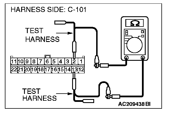
4. Measure the resistance between joint connector (4) terminals 2 and 13.
OK: 1 kohms or more
Q: Does the resistance measure 1 kohms or more?
YES : [The resistance measures 1 kohms or more] Go to Step 33.
NO : [The resistance measures less than 1 kohms] Go to Step 30.
STEP 30. Check steering wheel sensor connector C-312 for loose, corroded or damaged terminals, or terminals pushed back in the connector.

CAUTION: The strand end of the twist wire should be within 10 cm (4 inches) from the connector.
Q: Is steering wheel sensor connector C-312 in good condition?
YES : Go to Step 31.
NO : Repair the damaged parts.
STEP 31. Check the CAN_L and H lines (communication lines only) between joint connector (4) and the steering wheel sensor for short circuit. Measure the resistance at joint connector (4) C-101.
CAUTION:
- A digital multimeter should be used.
- The test wiring harness should be used.
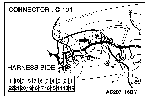

1. Disconnect joint connector (4) C-101 and steering wheel sensor connector C-312, and measure the resistance at the wiring harness side of joint connector (4) C-101.
2. Turn the ignition switch to the "LOCK" (OFF) position.
CAUTION: Disconnect the negative battery terminal.
3. Disconnect the negative battery terminal.
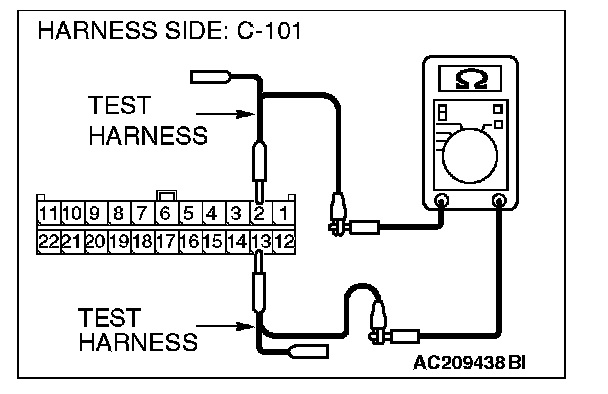
4. Measure the resistance between joint connector (4) terminals 2 and 13.
OK: 1 kohms or more
CAUTION: Strictly observe the specified wiring harness repair procedure.
Q: Does the resistance measure 1 kohms or more?
YES : [The resistance measures 1 kohms or more] Go to Step 32.
NO : [The resistance measures less than 1 kohms] Repair the wiring harness between joint connector (4) and steering wheel sensor connector.
STEP 32. Check the steering wheel sensor for short circuit. Measure the resistance at steering wheel sensor connector C-312.
CAUTION: A digital multimeter should be used.
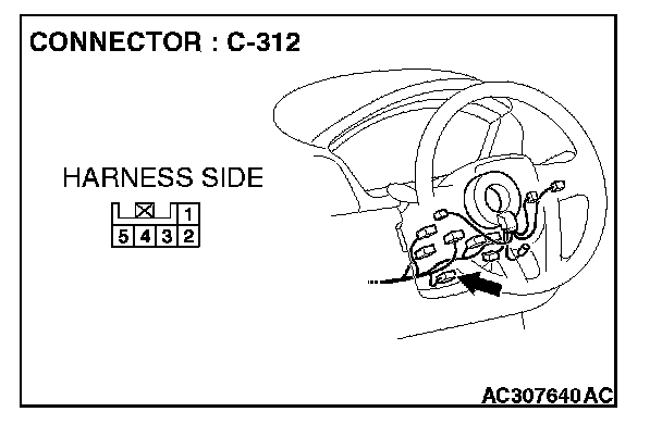
1. Disconnect steering wheel sensor connector C-312, and measure the resistance at the equipment side of steering wheel sensor connector C-312.
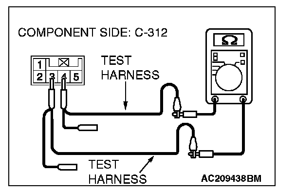
2. Measure the resistance between the steering wheel sensor connector terminals 3 and 4.
OK: 1 kohms or more
Q: Does the resistance measure 1 kohms or more?
YES : [The resistance measures 1 kohms or more] Diagnose CAN bus lines thoroughly by referring to Diagnostic Item 9. Diagnostic Item 9
NO : [The resistance measures lower than 1 kohms] Replace the steering wheel sensor.
STEP 33. Check data link connector C-121 for loose, corroded or damaged terminals, or terminals pushed back in the connector.
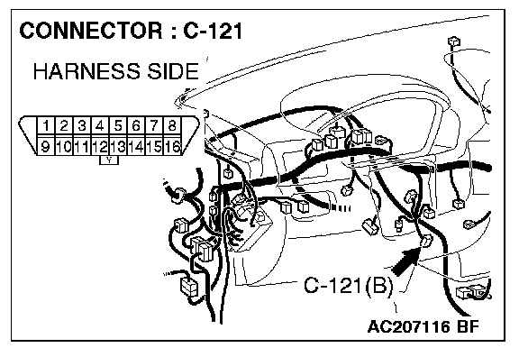
CAUTION: The strand end of the twist wire should be within 10 cm (4 inches) from the connector.
Q: Is data link connector C-121 in good condition?
YES : Go to Step 34.
NO : Repair the damaged parts.
STEP 34. Check the CAN_L and H lines (communication lines only) between joint connector (4) and the data link connector for short circuit. Measure the resistance at joint connector (4) C-101.
CAUTION:
- A digital multimeter should be used.
- The test wiring harness should be used.

1. Disconnect joint connector (4) C-101, and measure the resistance at the wiring harness side of joint connector (4) C-101.
2. Turn the ignition switch to the "LOCK" (OFF) position.
CAUTION: Disconnect the negative battery terminal.
3. Disconnect the negative battery terminal.
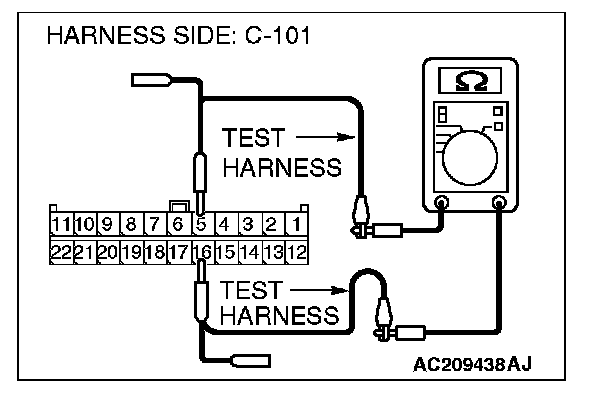
4. Measure the resistance between joint connector (4) terminals 5 and 16.
OK: 1 kohms or more
Q: Does the resistance measure 1 kohms or more?
YES : [The resistance measures 1 kohms or more] Go to Step 35.
NO : [The resistance measures less than 1 kohms] Repair the wiring harness between joint connector (4) and the data link connector.
STEP 35. Check the CAN_L and H lines (communication lines only) between joint connector (4) and the intermediate connector for short circuit. Measure the resistance at joint connector (4) C-101.
CAUTION:
- A digital multimeter should be used.
- The test wiring harness should be used.
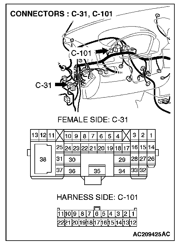
1. Disconnect intermediate connector C-31 and joint connector (4) C-101, and measure the resistance at the wiring harness side of joint connector (4) C-101.
2. Turn the ignition switch to the "LOCK" (OFF) position.
CAUTION: Disconnect the negative battery terminal.
3. Disconnect the negative battery terminal.
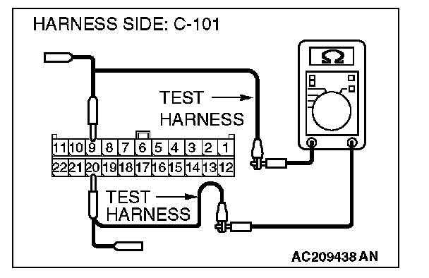
4. Measure the resistance between joint connector (4) terminals 9 and 20.
OK: 1 kohms or more
CAUTION: Strictly observe the specified wiring harness repair procedure.
Q: Does the resistance measure 1 kohms or more?
YES : [The resistance measures 1 kohms or more] Diagnose CAN bus lines thoroughly by referring to Diagnostic Item 9. Diagnostic Item 9
NO : [The resistance measures less than 1 kohms] Repair the wiring harness between intermediate connector C-31 and joint connector (4).
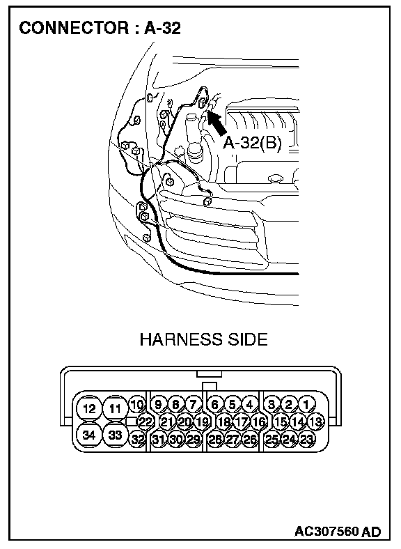
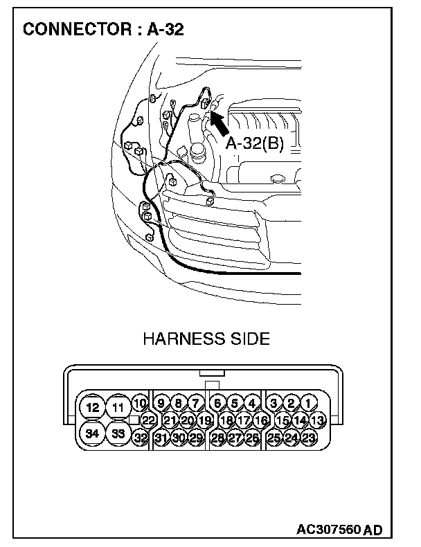
STEP 36. Check TCL/ASC-ECU connector A-32 for loose, corroded or damaged terminals, or terminals pushed back in the connector.

CAUTION: The strand end of the twist wire should be within 10 cm (4 inches) from the connector.
Q: Is TCL/ASC-ECU connector A-32 in good condition?
YES : Go to Step 37.
NO : Repair the damaged parts.
STEP 37. Check the CAN_L and H lines (communication lines only) between the TCL/ASC-ECU connector and the intermediate connector for short circuit. Measure the resistance at intermediate connector C-31.
CAUTION:
- A digital multimeter should be used.
- The test wiring harness should be used.
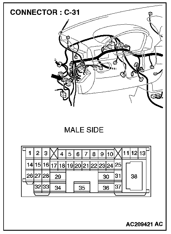
1. Disconnect intermediate connector C-31 and TCL/ASC-ECU connector A-32, and measure the resistance at the male side of intermediate connector C-31 (at front wiring harness side).
2. Turn the ignition switch to the "LOCK" (OFF) position.
CAUTION: Disconnect the negative battery terminal.
3. Disconnect the negative battery terminal.
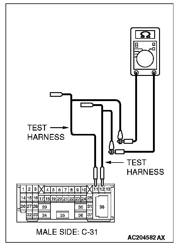
4. Measure the resistance between intermediate connector C-31 terminals 11 and 12.
OK: 1 kohms or more
Q: Does the resistance measure 1 kohms or more?
YES : [The resistance measures 1 kohms or more] Go to Step 38.
NO : [The resistance measures less than 1 kohms] Repair the wiring harness between intermediate connector C-31 and TCL/ASC-ECU connector.
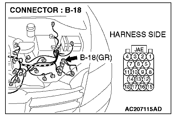
STEP 38. Check powertrain control module connector B-18 for loose, corroded or damaged terminals, or terminals pushed back in the connector.
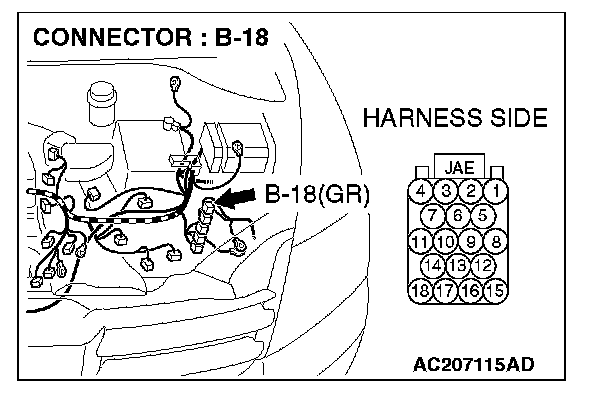
CAUTION: The strand end of the twist wire should be within 10 cm (4 inches) from the connector.
Q: Is powertrain control module connector B-18 in good condition?
YES : Go to Step 39.
NO : Repair the damaged parts.
STEP 39. Check the CAN_L and H lines (communication lines only) between the powertrain control module connector and the TCL/ASC-ECU connector for short circuit. Measure the resistance at powertrain control module connector B-18.
CAUTION:
- A digital multimeter should be used.
- The test wiring harness should be used.
1. Disconnect powertrain control module connector B-18 and TCL/ASC-ECU connector A-32, and measure the resistance at the harness side of powertrain control module connector B-18.
2. Turn the ignition switch to the "LOCK" (OFF) position.
CAUTION: Disconnect the negative battery terminal.
3. Disconnect the negative battery terminal.
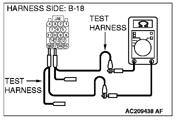
4. Measure the resistance between powertrain control module connector terminals 17 and 18.
OK: 1 kohms or more
CAUTION: Strictly observe the specified wiring harness repair procedure.
Q: Does the resistance measure 1 kohms or more?
YES : [The resistance measures 1 kohms or more] Go to Step 40.
NO : [The resistance measures less than 1 kohms] Repair the wiring harness between powertrain control module connector and TCL/ASC-ECU connector.
STEP 40. Check the TCL/ASC-ECU for short circuit. Measure the resistance at TCL/ASC-ECU connector A-32.
CAUTION: A digital multimeter should be used.

1. Disconnect TCL/ASC-ECU connector A-32, and measure the resistance at the equipment side of TCL/ASC-ECU connector A-32.
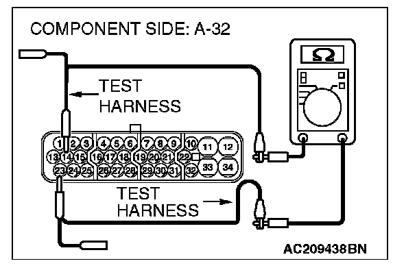
2. Measure the resistance between TCL/ASC-ECU connector terminals 14 and 23.
OK: 1 kohms or more
Q: Does the resistance measure 1 kohms or more?
YES : [The resistance measures 1 kohms or more] Go to Step 41.
NO : [The resistance measures less than 1 kohms] Replace the TCL/ASC-ECU.
STEP 41. Check the powertrain control module for short circuit. Measure the resistance at powertrain control module connector B-18.
CAUTION: A digital multimeter should be used.
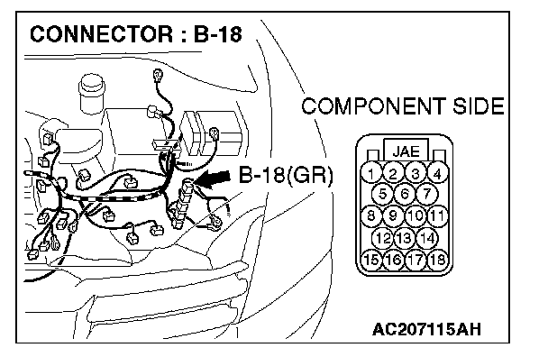
1. Disconnect powertrain control module connector B-18, and measure the resistance at the equipment side of powertrain control module connector B-18.
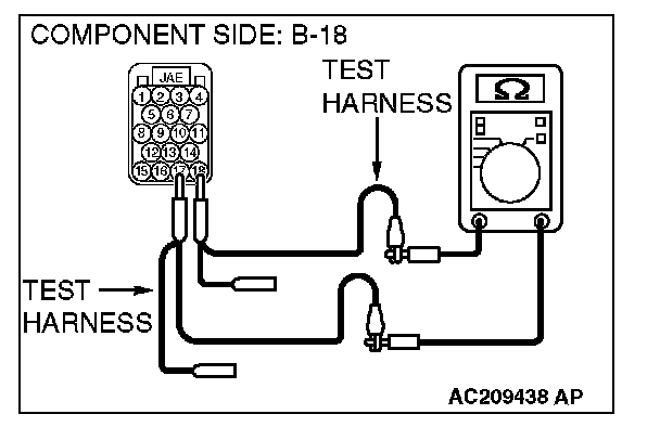
2. Measure the resistance between powertrain control module connector terminals 17 and 18.
OK: 120 ± 20 ohms
Q: Does the resistance measure 120 ± 20 ohms?
YES : [The resistance measures 120 ± 20 ohms] Diagnose CAN bus lines thoroughly by referring to Diagnostic Item 9. Diagnostic Item 9
NO : [The resistance does not measure 120 ± 20 ohms] Replace the powertrain control module.