Diagnostic Item 13
DIAGNOSTIC ITEM 13: Diagnose the lines between the ETACS-ECU and joint connector (CAN2).CAUTION: When servicing a CAN bus line, ground yourself by touching a metal object such as an unpainted water pipe. If you fail to do so, a component connected to the CAN bus line may be damaged.
CAN Communication Circuit (Part 1):
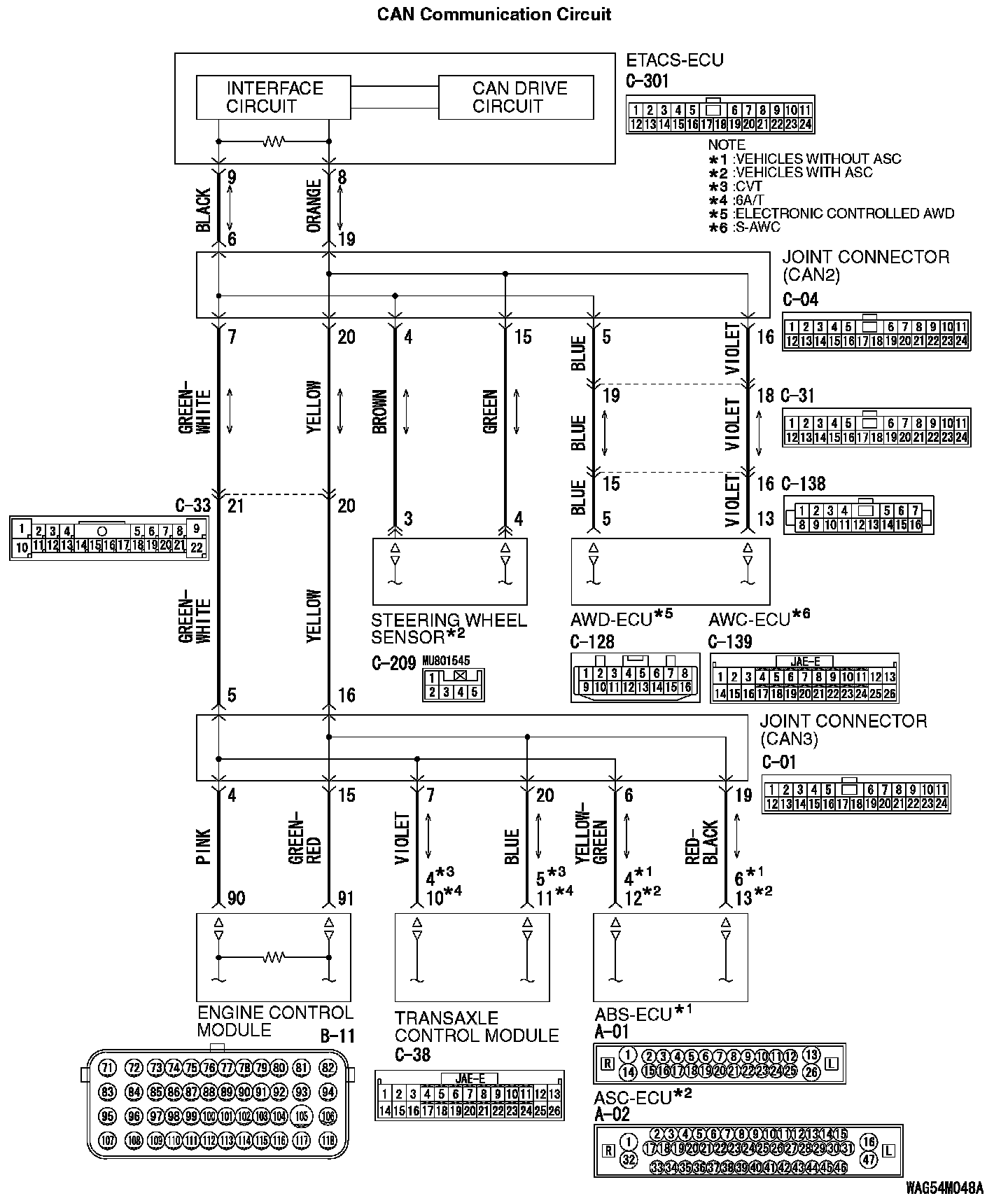
CAN Communication Circuit (Part 2):
FUNCTION
If a failure is present in the wiring harness between the ETACS-ECU connector and the joint connector (CAN2), this diagnosis result will be set.
TROUBLE JUDGMENT CONDITIONS
If a communication flag is not set for some of the ECUs on the CAN-C line, the ETACS-ECU determines that there is a failure.
TROUBLESHOOTING HINTS
- Malfunction of the connector [joint connector (CAN2) or ETACS-ECU connector improperly connected]
- Malfunction of the wiring harness [open circuit between the ETACS-ECU connector and the joint connector (CAN2), power supply circuit to the engine control module]
- Malfunction of the ETACS-ECU
DIAGNOSIS
Required Special Tools:
- MB991223: Harness Set
- MB992006: Extra Fine Probe
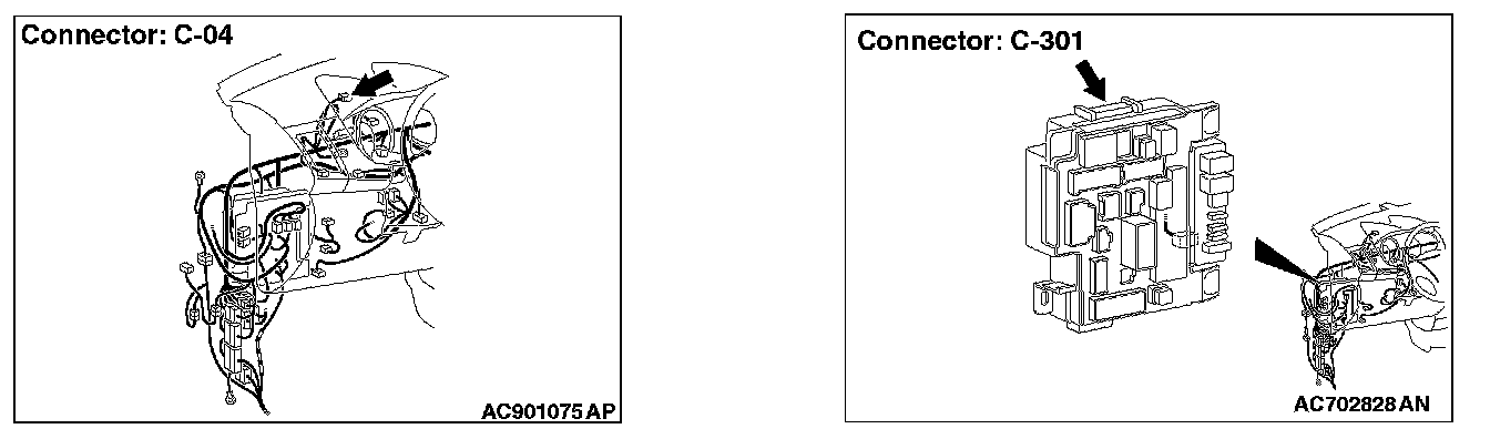
STEP 1. Check joint connector (CAN2) C-04 and ETACS-ECU connector C-301 for loose, corroded or damaged terminals, or terminals pushed back in the connector.
CAUTION: The strand end of the twisted wire should be within 10 cm (4 inches) from the connector.
Q: Are joint connector (CAN2) C-04 and ETACS-ECU connector C-301 in good condition?
YES : Go to Step 2.
NO : Repair the damaged parts.
STEP 2. Check the wiring harness between joint connector (CAN2) C-04 and ETACS-ECU connector C-301 for open circuit.
CAUTION: Strictly observe the specified wiring harness repair procedure.
1. Disconnect joint connector (CAN2) C-04 and ETACS-ECU connector C-301, and check the wiring harness.
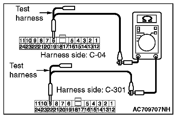
2. Check the wiring harness between joint connector (CAN2) C-04 (terminal No.6) and ETACS-ECU connector C-301 (terminal No.9)
OK: Continuity exists (2 ohms or less)
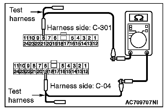
3. Check the wiring harness between joint connector (CAN2) C-04 (terminal No.19) and ETACS-ECU connector C-301 (terminal No.8)
OK: Continuity exists (2 ohms or less)
Q: Is the wiring harness between joint connector (CAN2) C-04 and ETACS-ECU connector C-301 in good condition?
YES : Go to Step 3.
NO : Repair the wiring harness between joint connector (CAN2) C-04 and ETACS-ECU connector C-301.
STEP 3. Using scan tool MB991958, diagnose the CAN bus line.
CAUTION: To prevent damage to scan tool MB991958, always turn the ignition switch to the "LOCK" (OFF) position before connecting or disconnecting scan tool MB991958.
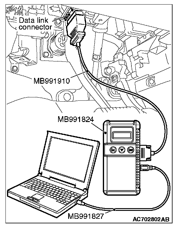
1. Connect scan tool MB991958 to the data link connector.
2. Turn the ignition switch to the "ON" position.
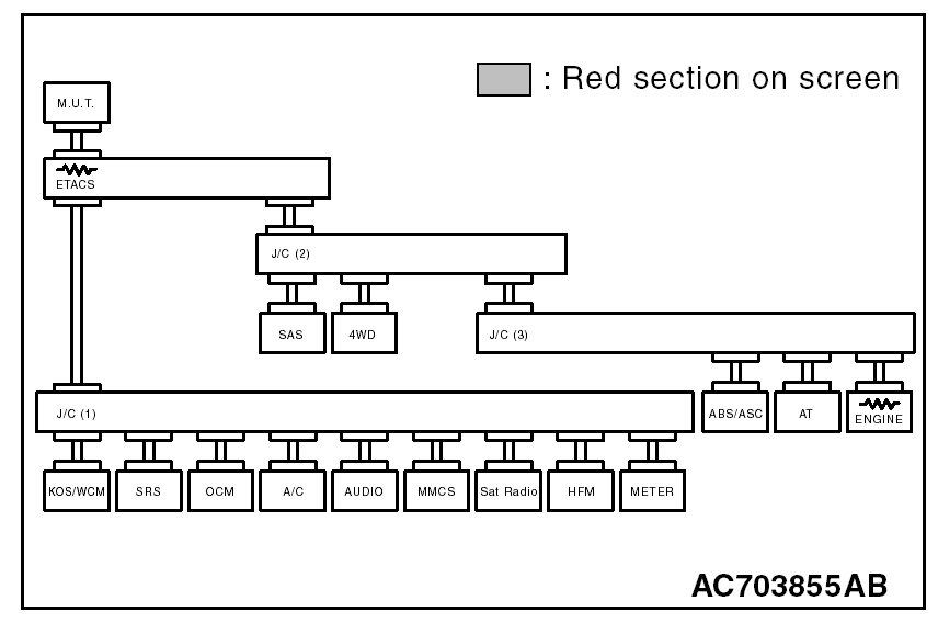
3. Diagnose CAN bus lines, and check if the scan tool screen is as shown in the illustration.
Q: Does the scan tool screen correspond to the illustration?
YES : The trouble can be an intermittent malfunction
NO : Replace the ETACS-ECU.