Diagnostic Item 22
DIAGNOSTIC ITEM 22: Diagnose when the scan tool cannot receive the data sent by CAN box unit [vehicles with MMCS].CAUTION: When servicing a CAN bus line, ground yourself by touching a metal object such as an unpainted water pipe. If you fail to do so, a component connected to the CAN bus line may be damaged.
CAN Communication Circuit (Part 1):
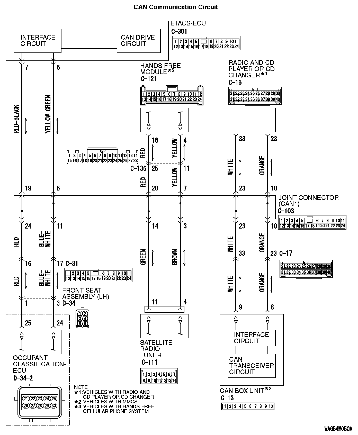
CAN Communication Circuit (Part 2):
FUNCTION
If the scan tool MB991958 cannot communicate with the CAN box unit, this diagnosis result will be set.
TROUBLE JUDGMENT CONDITIONS
If a communication flag is not set for the CAN box unit, the ETACS-ECU determines that there is a failure.
TROUBLESHOOTING HINTS
- Malfunction of the connector [joint connector (CAN1), CAN box unit connector improperly connected]
- Malfunction of the wiring harness [open circuit between the CAN box unit connector and the joint connector (CAN1), power supply circuit to the CAN box unit]
- Malfunction of the CAN box unit
DIAGNOSIS
Required Special Tools:
- MB991223: Harness Set
- MB992006: Extra Fine Probe
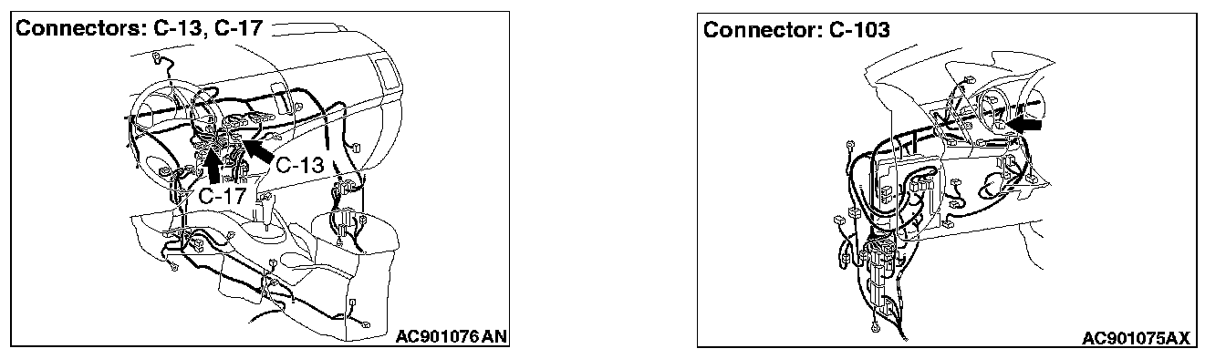
STEP 1. Check joint connector (CAN1) C-103, CAN box unit connector C-13 and intermediate connector C-17 for loose, corroded or damaged terminals, or terminals pushed back in the connector.
CAUTION: The strand end of the twisted wire should be within 10 cm (4 inches) from the connector.
Q: Are joint connector (CAN1) C-103, CAN box unit connector C-13 and intermediate connector C-17 in good condition?
YES : Go to Step 2.
NO : Repair the damaged parts.
STEP 2. Check the wiring harness between joint connector (CAN1) C-103 and CAN box unit connector C-13 for open circuit.
CAUTION: Strictly observe the specified wiring harness repair procedure.
1. Disconnect joint connector (CAN1) C-103 and CAN box unit connector C-13, and check the wiring harness.
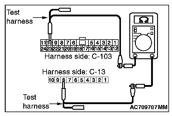
2. Check the wiring harness between joint connector (CAN1) C-103 (terminal No.10) and CAN box unit connector C-13 (terminal No.8)
OK: Continuity exists (2 ohms or less)
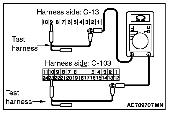
3. Check the wiring harness between joint connector (CAN1) C-103 (terminal No.23) and CAN box unit connector C-13 (terminal No.9)
OK: Continuity exists (2 ohms or less)
Q: Is the wiring harness between joint connector (CAN1) C-103 and CAN box unit connector C-13 in good condition?
YES : Check the power supply circuit of the CAN box unit. Refer to MMCS - Diagnosis. Trouble Symptom Chart
NO : Repair the wiring harness between joint connector (CAN1) C-103 and CAN box unit connector C-13.