Part 2
STEP 32. Check the wiring harness between joint connector (CAN1) C-103 and A/C-ECU connector C-109 for line-to-line short. Measure the resistance at joint connector (CAN1) C-103.1. Disconnect joint connector (CAN1), and check that there is continuity at the harness side of joint connector (CAN1).
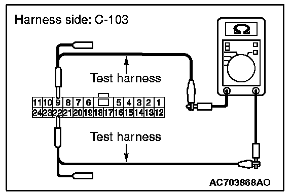
2. Check that there is continuity between joint connector (CAN1) terminals 9 and 22.
OK: No continuity
Q: Is the check result normal?
YES (vehicles without MMCS) : Go to Step 33.
YES (vehicles with MMCS) : Go to Step 34.
NO : Go to Step 54.
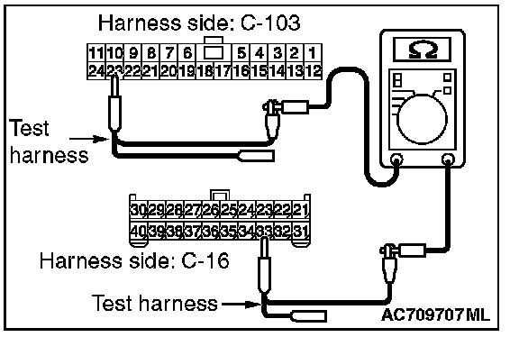
STEP 33. Check the wiring harness between joint connector (CAN1) C-103 and radio and CD player or radio and CD changer connector C-16 for line-to-line short. Measure the resistance at joint connector (CAN1) C-103.
1. Disconnect joint connector (CAN1), and check that there is continuity at the harness side of joint connector (CAN1).
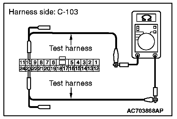
2. Check that there is continuity between joint connector (CAN1) terminals 10 and 23.
OK: No continuity
Q: Is the check result normal?
YES (vehicles without satellite radio) : Go to Step 36.
YES (vehicles with satellite radio) : Go to Step 35.
NO : Go to Step 55.
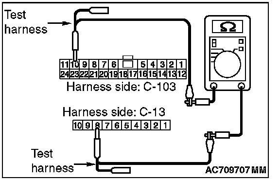
STEP 34. Check the wiring harness between joint connector (CAN1) C-103 and CAN box unit connector C-13 for line-to-line short. Measure the resistance at joint connector (CAN1) C-103.
1. Disconnect joint connector (CAN1), and check that there is continuity at the harness side of joint connector (CAN1).
2. Check that there is continuity between joint connector (CAN1) terminals 10 and 23.
OK: No continuity
Q: Is the check result normal?
YES (vehicles without satellite radio) : Go to Step 36.
YES (vehicles with satellite radio) : Go to Step 35.
NO : Go to Step 56.
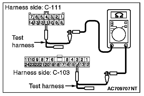
STEP 35. Check the wiring harness between joint connector (CAN1) C-103 and satellite radio tuner connector C-111 for line-to-line short. Measure the resistance at joint connector (CAN1) C-103.
1. Disconnect joint connector (CAN1), and check that there is continuity at the harness side of joint connector (CAN1).
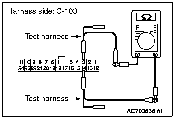
2. Check that there is continuity between joint connector (CAN1) terminals 3 and 14.
OK: No continuity
Q: Is the check result normal?
YES : Go to Step 36.
NO : Go to Step 57.
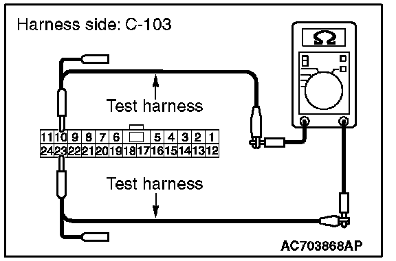
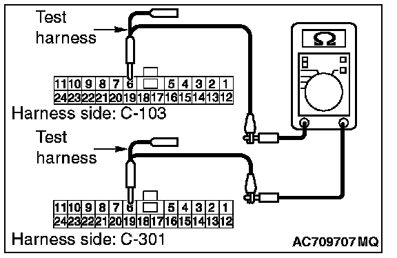
STEP 36. Check the wiring harness between joint connector (CAN1) C-103 and EATCS-ECU connector C-301 for line-to-line short. Measure the resistance at joint connector (CAN1) C-103.
CAUTION: Strictly observe the specified wiring harness repair procedure.
1. Disconnect joint connector (CAN1) and ETACS-ECU connector C-301, and check that there is continuity at the harness side of joint connector (CAN1).
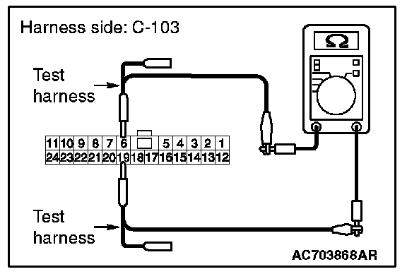
2. Check that there is continuity between joint connector (CAN1) terminals 6 and 19.
OK: No continuity
Q: Is the check result normal?
YES : Go to Step 58.
NO : Repair the wiring harness between joint connector (CAN1) C-103 and ETACS-ECU connector C-301.
STEP 37. Check the wiring harness between joint connector (CAN1) C-103 and combination meter connector C-03 for open circuit.
CAUTION: Strictly observe the specified wiring harness repair procedure.
1. Disconnect joint connector (CAN1) C-103 and combination meter connector C-03, and check the wiring harness.
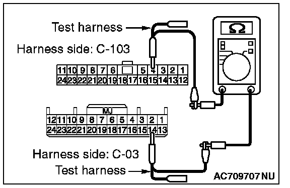
2. Check the wiring harness between joint connector (CAN1) C-103 (terminal No.4) and combination meter connector C-03 (terminal No.14)
OK: Continuity exists (2 ohms or less)
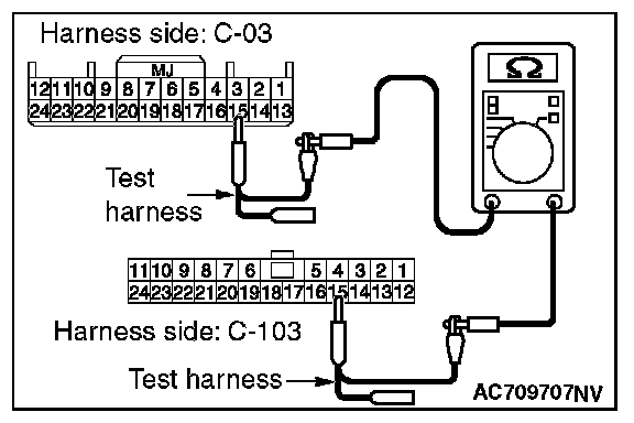
3. Check the wiring harness between joint connector (CAN1) C-103 (terminal No.15) and combination meter connector C-03 (terminal No.15)
OK: Continuity exists (2 ohms or less)
Q: Is the wiring harness between joint connector (CAN1) C-103 and combination meter connector C-03 in good condition?
YES (vehicles with KOS) : Go to Step 38.
YES (vehicles with WCM) : Go to Step 39.
NO (vehicles with KOS or WCM) : Repair the wiring harness between joint connector (CAN1) C-103 and combination meter connector C-03.
STEP 38. Check the wiring harness between joint connector (CAN1) C-103 and KOS-ECU connector C-102 for open circuit.
CAUTION: Strictly observe the specified wiring harness repair procedure.
1. Disconnect joint connector (CAN1) C-103 and KOS-ECU connector C-102, and check the wiring harness.
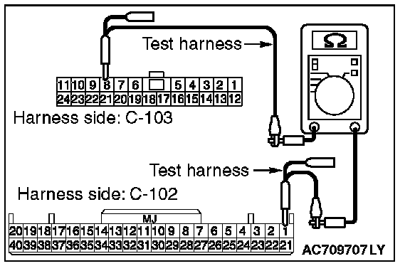
2. Check the wiring harness between joint connector (CAN1) C-103 (terminal No.8) and KOS-ECU connector C-102 (terminal No.1)
OK: Continuity exists (2 ohms or less)
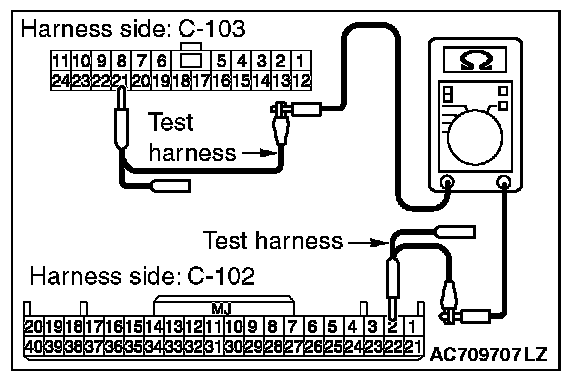
3. Check the wiring harness between joint connector (CAN1) C-103 (terminal No.21) and KOS-ECU connector C-102 (terminal No.2)
OK: Continuity exists (2 ohms or less)
Q: Is the wiring harness between joint connector (CAN1) C-103 and KOS-ECU connector C-102 in good condition?
YES : Go to Step 40.
NO : Repair the wiring harness between joint connector (CAN1) C-103 and KOS-ECU connector C-102.
STEP 39. Check the wiring harness between joint connector (CAN1) C-103 and WCM connector C-29 for open circuit.
CAUTION: Strictly observe the specified wiring harness repair procedure.
1. Disconnect joint connector (CAN1) C-103 and WCM connector C-29, and check the wiring harness.
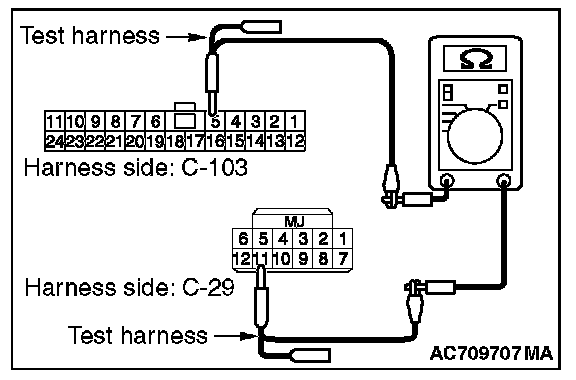
2. Check the wiring harness between joint connector (CAN1) C-103 (terminal No.5) and WCM connector C-29 (terminal No.11)
OK: Continuity exists (2 ohms or less)
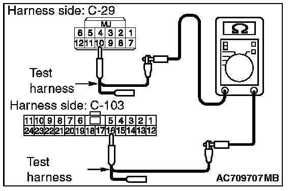
3. Check the wiring harness between joint connector (CAN1) C-103 (terminal No.16) and WCM connector C-29 (terminal No.2)
OK: Continuity exists (2 ohms or less)
Q: Is the wiring harness between joint connector (CAN1) C-103 and WCM connector C-29 in good condition?
YES : Go to Step 40.
NO : Repair the wiring harness between joint connector (CAN1) C-103 and WCM connector C-29.
STEP 40. Check the wiring harness between joint connector (CAN1) C-103 and SRS-ECU connector C-28 for open circuit.
CAUTION: Strictly observe the specified wiring harness repair procedure.
1. Disconnect joint connector (CAN1) C-103 and SRS-ECU connector C-28, and check the wiring harness.
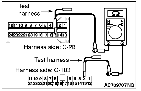
2. Check the wiring harness between joint connector (CAN1) C-103 (terminal No.2) and SRS-ECU connector C-28 (terminal No.15)
OK: Continuity exists (2 ohms or less)
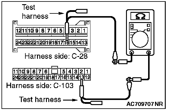
3. Check the wiring harness between joint connector (CAN1) C-103 (terminal No.13) and SRS-ECU connector C-28 (terminal No.16)
OK: Continuity exists (2 ohms or less)
Q: Is the wiring harness between joint connector (CAN1) C-103 and SRS-ECU connector C-28 in good condition?
YES : Go to Step 41.
NO : Repair the wiring harness between joint connector (CAN1) C-103 and SRS-ECU connector C-28.
STEP 41. Check the wiring harness between joint connector (CAN1) C-103 and occupant classification-ECU connector D-34-2 for open circuit.
CAUTION: Strictly observe the specified wiring harness repair procedure.
1. Disconnect joint connector (CAN1) C-103 and occupant classification-ECU connector D-34-2, and check the wiring harness.
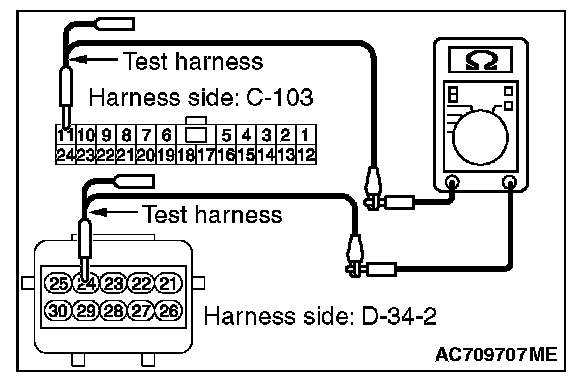
2. Check the wiring harness between joint connector (CAN1) C-103 (terminal No.11) and occupant classification-ECU connector D-34-2 (terminal No.24)
OK: Continuity exists (2 ohms or less)
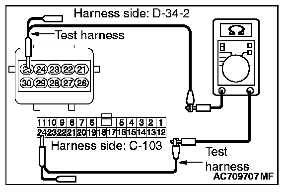
3. Check the wiring harness between joint connector (CAN1) C-103 (terminal No.24) and occupant classification-ECU connector D-34-2 (terminal No.25)
OK: Continuity exists (2 ohms or less)
Q: Is the wiring harness between joint connector (CAN1) C-103 and occupant classification-ECU connector D-34-2 in good condition?
YES (vehicles without hands-free cellular phone system) : Go to Step 43.
YES (vehicles with hands-free cellular phone system) : Go to Step 42.
NO : Repair the wiring harness between joint connector (CAN1) C-103 and occupant classification-ECU connector D-34-2.
STEP 42. Check the wiring harness between joint connector (CAN1) C-103 and hands free module connector C-121 for open circuit.
CAUTION: Strictly observe the specified wiring harness repair procedure.
1. Disconnect joint connector (CAN1) C-103 and occupant hands free module connector C-121, and check the wiring harness.
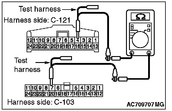
2. Check the wiring harness between joint connector (CAN1) C-103 (terminal No.7) and hands free module connector C-121 (terminal No.4)
OK: Continuity exists (2 ohms or less)
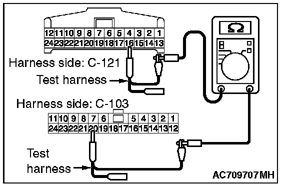
3. Check the wiring harness between joint connector (CAN1) C-103 (terminal No.20) and hands free module connector C-121 (terminal No.16)
OK: Continuity exists (2 ohms or less)
Q: Is the wiring harness between joint connector (CAN1) C-103 and hands free module connector C-121 in good condition?
YES : Go to Step 43.
NO : Repair the wiring harness between joint connector (CAN1) C-103 and hands free module connector C-121.
STEP 43. Check the wiring harness between joint connector (CAN1) C-103 and A/C-ECU connector C-109 for open circuit.
CAUTION: Strictly observe the specified wiring harness repair procedure.
1. Disconnect joint connector (CAN1) C-103 and A/C-ECU connector C-109, and check the wiring harness.
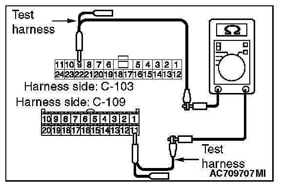
2. Check the wiring harness between joint connector (CAN1) C-103 (terminal No.9) and A/C-ECU connector C-109 (terminal No.11)
OK: Continuity exists (2 ohms or less)
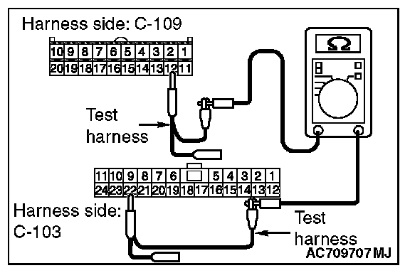
3. Check the wiring harness between joint connector (CAN1) C-103 (terminal No.22) and A/C-ECU connector C-109 (terminal No.12)
OK: Continuity exists (2 ohms or less)
Q: Is the wiring harness between joint connector (CAN1) C-103 and A/C-ECU connector C-109 in good condition?
YES (vehicles without MMCS) : Go to Step 44.
YES (vehicles with MMCS) : Go to Step 45.
NO : Repair the wiring harness between joint connector (CAN1) C-103 and A/C-ECU connector C-109.
STEP 44. Check the wiring harness between joint connector (CAN1) C-103 and radio and CD player or CD changer connector C-16 for open circuit.
CAUTION: Strictly observe the specified wiring harness repair procedure.
1. Disconnect joint connector (CAN1) C-103 and radio and CD player or CD changer connector C-16, and check the wiring harness.
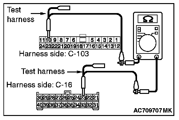
2. Check the wiring harness between joint connector (CAN1) C-103 (terminal No.10) and radio and CD player or CD changer connector C-16 (terminal No.23)
OK: Continuity exists (2 ohms or less)
3. Check the wiring harness between joint connector (CAN1) C-103 (terminal No.23) and radio and CD player or CD changer connector C-16 (terminal No.33)
OK: Continuity exists (2 ohms or less)
Q: Is the wiring harness between joint connector (CAN1) C-103 and radio and CD player or CD changer connector C-16 in good condition?
YES (vehicles without satellite radio) : Go to Step 47.
YES (vehicles with satellite radio) : Go to Step 46.
NO : Repair the wiring harness between joint connector (CAN1) C-103 and radio and CD player or CD changer connector C-16
STEP 45. Check the wiring harness between joint connector (CAN1) C-103 and CAN box unit connector C-13 for open circuit.
CAUTION: Strictly observe the specified wiring harness repair procedure.
1. Disconnect joint connector (CAN1) C-103 and CAN box unit connector C-13, and check the wiring harness.
2. Check the wiring harness between joint connector (CAN1) C-103 (terminal No.10) and CAN box unit connector C-13 (terminal No.8)
OK: Continuity exists (2 ohms or less)
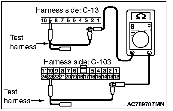
3. Check the wiring harness between joint connector (CAN1) C-103 (terminal No.23) and CAN box unit connector C-13 (terminal No.9)
OK: Continuity exists (2 ohms or less)
Q: Is the wiring harness between joint connector (CAN1) C-103 and CAN box unit connector C-13 in good condition?
YES (vehicles without satellite radio) : Go to Step 47.
YES (vehicles with satellite radio) : Go to Step 46.
NO : Repair the wiring harness between joint connector (CAN1) C-103 and CAN box unit connector C-13.
STEP 46. Check the wiring harness between joint connector (CAN1) C-103 and satellite radio tuner connector C-111 for open circuit.
CAUTION: Strictly observe the specified wiring harness repair procedure.
1. Disconnect joint connector (CAN1) C-103 and satellite radio tuner connector C-111, and check the wiring harness.
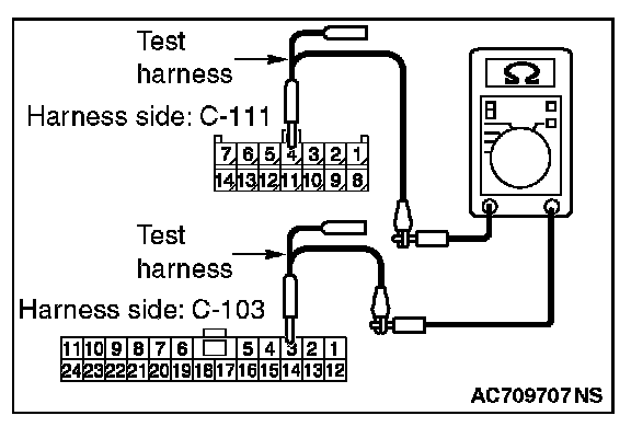
2. Check the wiring harness between joint connector (CAN1) C-103 (terminal No.3) and satellite radio tuner connector C-111 (terminal No.4)
OK: Continuity exists (2 ohms or less)
3. Check the wiring harness between joint connector (CAN1) C-103 (terminal No.14) and satellite radio tuner connector C-111 (terminal No.11)
OK: Continuity exists (2 ohms or less)
Q: Is the wiring harness between joint connector (CAN1) C-103 and satellite radio tuner connector C-111 in good condition?
YES : Go to Step 47.
NO : Repair the wiring harness between joint connector (CAN1) C-103 and satellite radio tuner connector C-111.
STEP 47. Check the wiring harness between joint connector (CAN1) C-103 and ETACS-ECU connector C-301 for open circuit.
CAUTION: Strictly observe the specified wiring harness repair procedure.
1. Disconnect joint connector (CAN1) C-103 and ETACS-ECU connector C-301, and check the wiring harness.
2. Check the wiring harness between joint connector (CAN1) C-103 (terminal No.6) and ETACS-ECU connector C-301 (terminal No.6)
OK: Continuity exists (2 ohms or less)
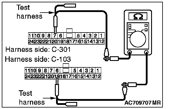
3. Check the wiring harness between joint connector (CAN1) C-103 (terminal No.19) and ETACS-ECU connector C-301 (terminal No.7)
OK: Continuity exists (2 ohms or less)
Q: Is the wiring harness between joint connector (CAN1) C-103 and ETACS-ECU connector C-301 in good condition?
YES : Go to Step 58.
NO : Repair the wiring harness between joint connector (CAN1) C-103 and ETACS-ECU connector C-301.
STEP 48. Using scan tool MB991958, diagnose the CAN bus line. (checking the combination meter for internal failure)
CAUTION:
- Strictly observe the specified wiring harness repair procedure.
- To prevent damage to scan tool MB991958, always turn the ignition switch to the "LOCK" (OFF) position before connecting or disconnecting scan tool MB991958.
1. Disconnect combination meter connector C-03.
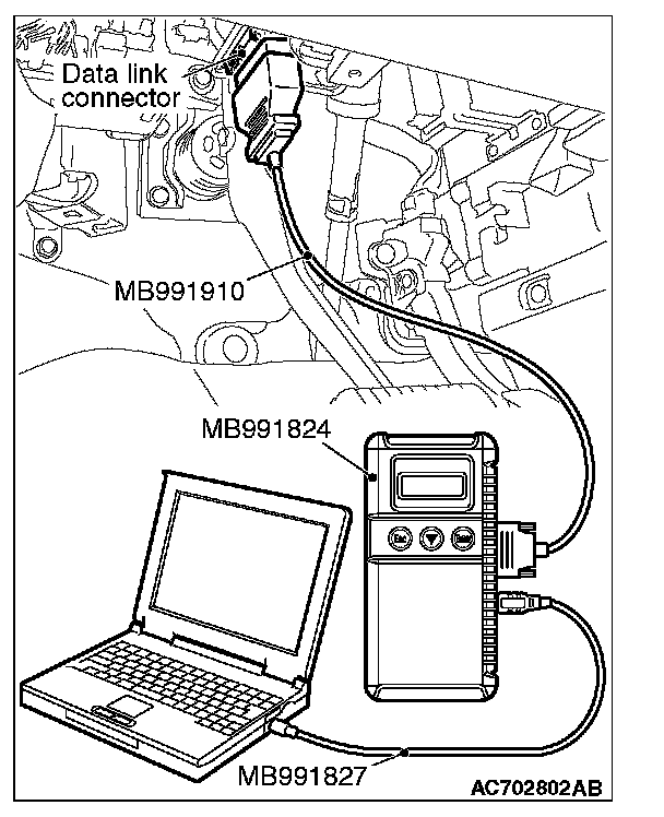
2. Connect scan tool MB991958 to the data link connector.
3. Turn the ignition switch to the "ON" position.
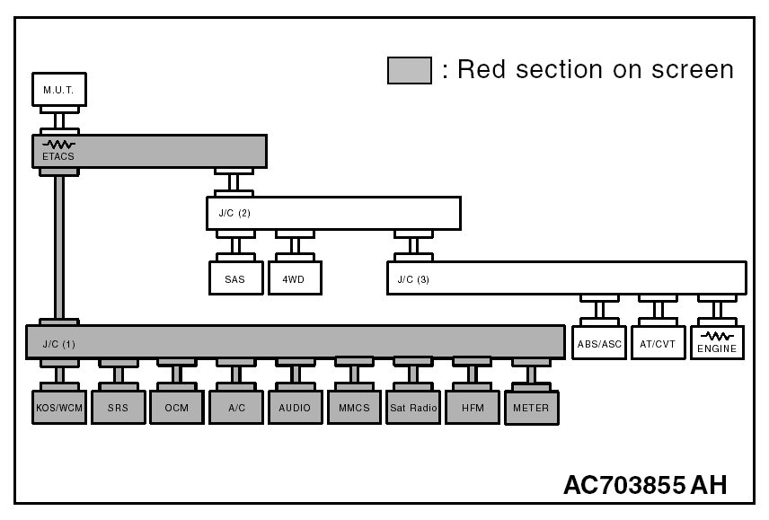
4. 6.Diagnose CAN bus lines, and check if the scan tool MB991958 screen is as shown in the figure.
OK: The display of the scan tool MB991958 is as shown in the figure.
Q: Does scan tool MB991958 screen correspond to the illustration?
YES : Repair the wiring harness between joint connector (CAN1) C-103 and combination meter connector C-03.
NO : Check combination meter connector C-03, and repair if necessary. If the combination meter connector is in good condition, replace the combination meter.