Part 3
STEP 49. Using scan tool MB991958, diagnose the CAN bus line. (checking the KOS-ECU for internal failure)CAUTION:
- Strictly observe the specified wiring harness repair procedure.
- To prevent damage to scan tool MB991958, always turn the ignition switch to the "LOCK" (OFF) position before connecting or disconnecting scan tool MB991958.
1. Disconnect KOS-ECU connector C-102.
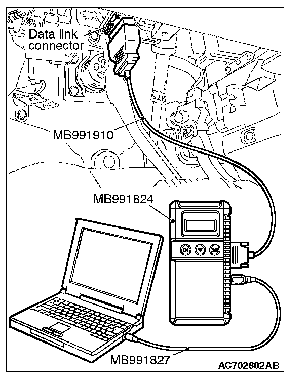
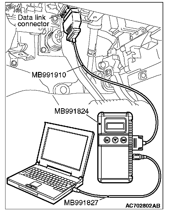
2. Connect scan tool MB991958 to the data link connector.
3. Turn the ignition switch to the "ON" position.

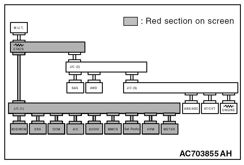
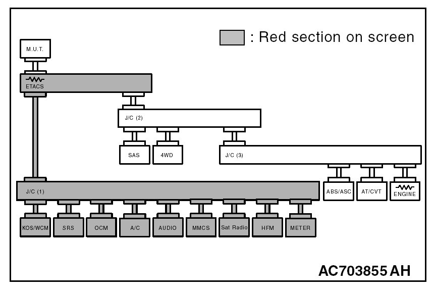
4. Diagnose CAN bus lines, and check if the scan tool MB991958 screen is as shown in the figure.
OK: The display of the scan tool MB991958 is as shown in the figure.
Q: Does scan tool MB991958 screen correspond to the illustration?
YES : Repair the wiring harness between joint connector (CAN1) C-103 and KOS-ECU connector C-102.
NO : Check KOS-ECU connector C-102, and repair if necessary. If the KOS-ECU connector is in good condition, replace the KOS-ECU.
STEP 50. Using scan tool MB991958, diagnose the CAN bus line. (checking the WCM for internal failure)
CAUTION:
- Strictly observe the specified wiring harness repair procedure.
- To prevent damage to scan tool MB991958, always turn the ignition switch to the "LOCK" (OFF) position before connecting or disconnecting scan tool MB991958.
1. Disconnect WCM connector C-29.
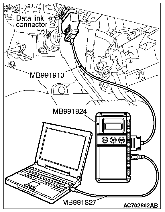
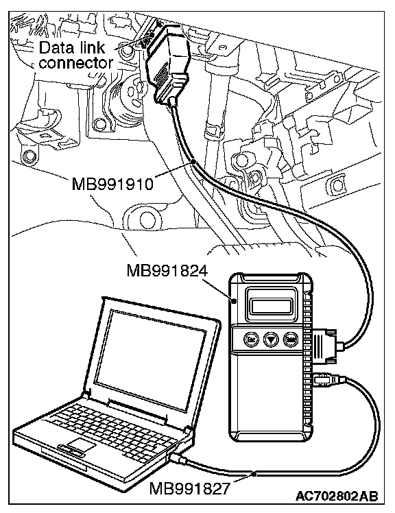
2. Connect scan tool MB991958 to the data link connector.
3. Turn the ignition switch to the "ON" position.

4. Diagnose CAN bus lines, and check if the scan tool MB991958 screen is as shown in the figure.
OK: The display of the scan tool MB991958 is as shown in the figure.
Q: Does scan tool MB991958 screen correspond to the illustration?
YES : Repair the wiring harness between joint connector (CAN1) C-103 and WCM connector C-29.
NO : Check WCM connector C-29, and repair if necessary. If the WCM connector is in good condition, replace the WCM.
STEP 51. Using scan tool MB991958, diagnose the CAN bus line. (checking the SRS-ECU for internal failure)
CAUTION:
- Strictly observe the specified wiring harness repair procedure.
- To prevent damage to scan tool MB991958, always turn the ignition switch to the "LOCK" (OFF) position before connecting or disconnecting scan tool MB991958.
1. Disconnect SRS-ECU connector C-28.
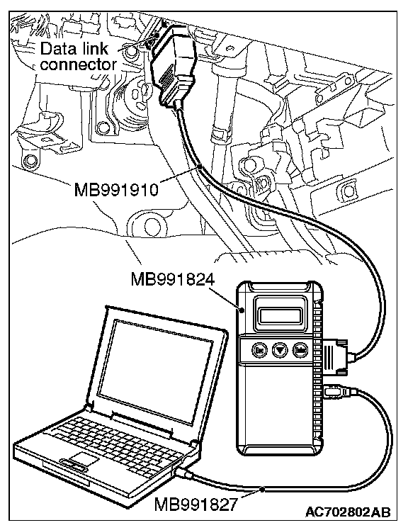
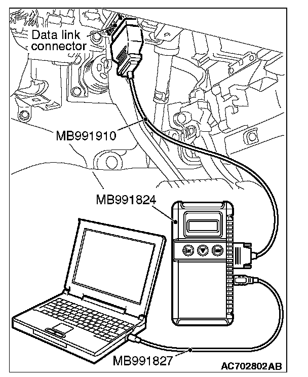
2. Connect scan tool MB991958 to the data link connector.
3. Turn the ignition switch to the "ON" position.
4. Diagnose CAN bus lines, and check if the scan tool MB991958 screen is as shown in the figure.
OK: The display of the scan tool MB991958 is as shown in the figure.
Q: Does scan tool MB991958 screen correspond to the illustration?
YES : Repair the wiring harness between joint connector (CAN1) C-103 and SRS-ECU connector C-28.
NO : Check SRS-ECU connector C-28, and repair if necessary. If the SRS-ECU connector is in good condition, replace the SRS-ECU.
STEP 52. Using scan tool MB991958, diagnose the CAN bus line. (checking the occupant classification-ECU for internal failure)
CAUTION:
- Strictly observe the specified wiring harness repair procedure.
- To prevent damage to scan tool MB991958, always turn the ignition switch to the "LOCK" (OFF) position before connecting or disconnecting scan tool MB991958.
1. Disconnect occupant classification-ECU connector D-34-2.
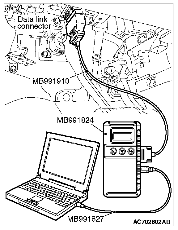
2. Connect scan tool MB991958 to the data link connector.
3. Turn the ignition switch to the "ON" position.

4. Diagnose CAN bus lines, and check if the scan tool MB991958 screen is as shown in the figure.
OK: The display of the scan tool MB991958 is as shown in the figure.
Q: Does scan tool MB991958 screen correspond to the illustration?
YES : Check intermediate connectors C-31 and D-34, and repair if necessary. If the intermediate connector is in good condition, repair the wiring harness between joint connector (CAN1) C-103 and occupant classification-ECU connector D-34-2.
NO : Check occupant classification-ECU connector D-34-2, and repair if necessary. If the occupant classification-ECU connector is in good condition, replace the occupant classification-ECU.
STEP 53. Using scan tool MB991958, diagnose the CAN bus line. (checking the hands free module for internal failure)
CAUTION:
- Strictly observe the specified wiring harness repair procedure.
- To prevent damage to scan tool MB991958, always turn the ignition switch to the "LOCK" (OFF) position before connecting or disconnecting scan tool MB991958.
1. Disconnect hands free module connector C-121.
2. Connect scan tool MB991958 to the data link connector.
3. Turn the ignition switch to the "ON" position.

4. Diagnose CAN bus lines, and check if the scan tool MB991958 screen is as shown in the figure.
OK: The display of the scan tool MB991958 is as shown in the figure.
Q: Does scan tool MB991958 screen correspond to the illustration?
YES : Check intermediate connector C-136, and repair if necessary. If the intermediate connector is in good condition, repair the wiring harness between joint connector (CAN1) C-103 and hands free module connector C-121.
NO : Check hands free module connector C-121, and repair if necessary. If the hands free module connector is in good condition, replace the hands free module.
STEP 54. Using scan tool MB991958, diagnose the CAN bus line. (checking the A/C-ECU for internal failure)
CAUTION:
- Strictly observe the specified wiring harness repair procedure.
- To prevent damage to scan tool MB991958, always turn the ignition switch to the "LOCK" (OFF) position before connecting or disconnecting scan tool MB991958.
1. Disconnect A/C-ECU connector C-109.
2. Connect scan tool MB991958 to the data link connector.
3. Turn the ignition switch to the "ON" position.

4. Diagnose CAN bus lines, and check if the scan tool MB991958 screen is as shown in the figure.
OK: The display of the scan tool MB991958 is as shown in the figure.
Q: Does scan tool MB991958 screen correspond to the illustration?
YES : Repair the wiring harness between joint connector (CAN1) C-103 and A/C-ECU connector C-109.
NO : Check A/C-ECU connector C-109, and repair if necessary. If the A/C-ECU connector is in good condition, replace the A/C-ECU.
STEP 55. Using scan tool MB991958, diagnose the CAN bus line. (checking the radio and CD player or radio and CD changer for internal failure)
CAUTION:
- Strictly observe the specified wiring harness repair procedure.
- To prevent damage to scan tool MB991958, always turn the ignition switch to the "LOCK" (OFF) position before connecting or disconnecting scan tool MB991958.
1. Disconnect radio and CD player or CD changer connector C-16.
2. Connect scan tool MB991958 to the data link connector.
3. Turn the ignition switch to the "ON" position.

4. Diagnose CAN bus lines, and check if the scan tool MB991958 screen is as shown in the figure.
OK: The display of the scan tool MB991958 is as shown in the figure.
Q: Does scan tool MB991958 screen correspond to the illustration?
YES : Repair the wiring harness between joint connector (CAN1) C-103 and radio and CD player or radio and CD changer connector C-16.
NO : Check radio and CD player or radio and CD changer connector C-16, and repair if necessary. If the radio and CD player or radio and CD changer connector is in good condition, replace the radio and CD player or radio and CD changer.
STEP 56. Using scan tool MB991958, diagnose the CAN bus line. (checking the CAN box unit for internal failure)
CAUTION:
- Strictly observe the specified wiring harness repair procedure.
- To prevent damage to scan tool MB991958, always turn the ignition switch to the "LOCK" (OFF) position before connecting or disconnecting scan tool MB991958.
1. Disconnect CAN box unit connector C-13.
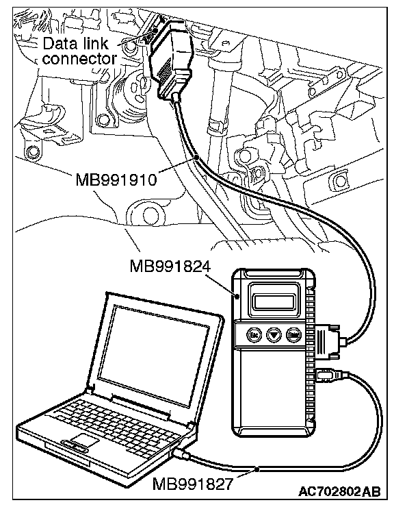
2. Connect scan tool MB991958 to the data link connector.
3. Turn the ignition switch to the "ON" position.
4. Diagnose CAN bus lines, and check if the scan tool MB991958 screen is as shown in the figure.
OK: The display of the scan tool MB991958 is as shown in the figure.
Q: Does scan tool MB991958 screen correspond to the illustration?
YES : Check intermediate connector C-17, and repair if necessary. If the intermediate connector is in good condition, repair the wiring harness between joint connector (CAN1) C-103 and CAN box unit connector C-13.
NO : Check CAN box unit connector C-13, and repair if necessary. If the CAN box unit connector is in good condition, replace the CAN box unit.
STEP 57. Using scan tool MB991958, diagnose the CAN bus line. (checking the satellite radio tuner for internal failure)
CAUTION:
- Strictly observe the specified wiring harness repair procedure.
- To prevent damage to scan tool MB991958, always turn the ignition switch to the "LOCK" (OFF) position before connecting or disconnecting scan tool MB991958.
1. Disconnect satellite radio tuner connector C-111.

2. Connect scan tool MB991958 to the data link connector.
3. Turn the ignition switch to the "ON" position.

4. Diagnose CAN bus lines, and check if the scan tool MB991958 screen is as shown in the figure.
OK: The display of the scan tool MB991958 is as shown in the figure.
Q: Does scan tool MB991958 screen correspond to the illustration?
YES : Repair the wiring harness between joint connector (CAN1) C-103 and satellite radio tuner connector C-111.
NO : Check satellite radio tuner connector C-111, and repair if necessary. If the satellite radio tuner connector is in good condition, replace the satellite radio tuner.
STEP 58. Using scan tool MB991958, diagnose the CAN bus line. (trouble symptom check)
CAUTION:
- Strictly observe the specified wiring harness repair procedure.
- To prevent damage to scan tool MB991958, always turn the ignition switch to the "LOCK" (OFF) position before connecting or disconnecting scan tool MB991958.

1. Connect scan tool MB991958 to the data link connector.
2. Turn the ignition switch to the "ON" position.
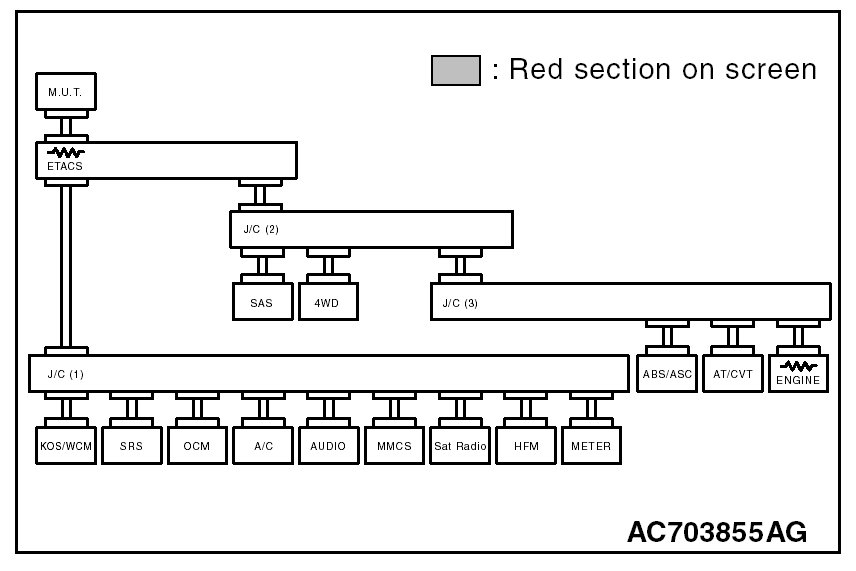
3. Diagnose CAN bus lines, and check if the scan tool MB991958 screen is as shown in the figure.
OK: The display of the scan tool MB991958 is as shown in the figure.
Q: Does scan tool MB991958 screen correspond to the illustration?
YES : The trouble can be an intermittent malfunction
NO : Check the ETACS-ECU connector C-301, and repair if necessary. If the ETACS-ECU connector is in good condition, replace the ETACS-ECU.