Traction Control/Active Stability Control System (TCL/ASC)
CHECK AT TCL/ASC-ECU
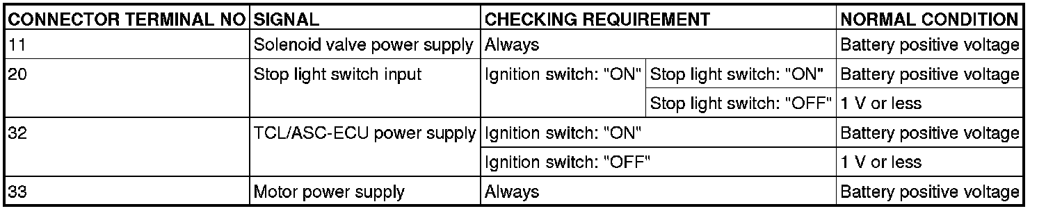
TERMINAL VOLTAGE CHECK CHART
Required Special Tool:
MB991952: ABS Check Harness
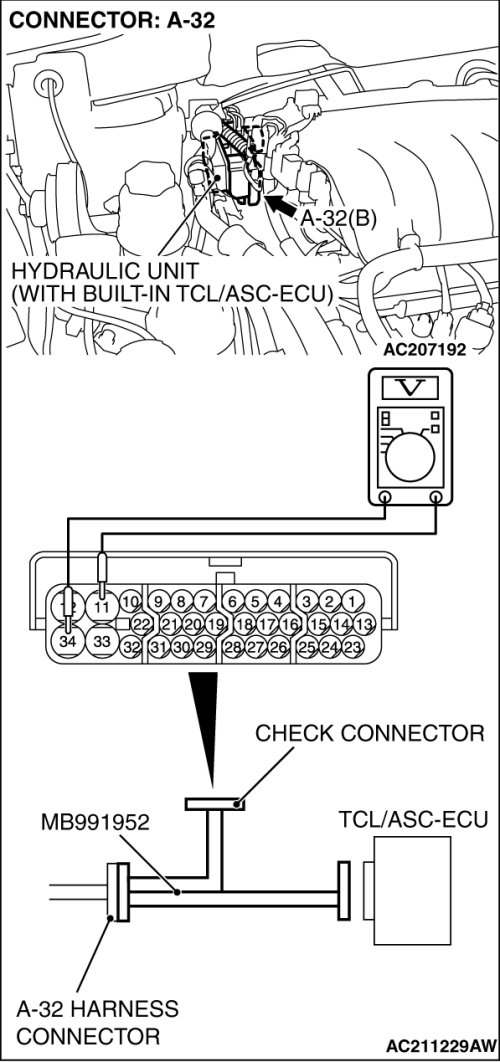
1. Disconnect the TCL/ASC-ECU connector A-32, and then use the special tool ABS Check Harness
(MB991952) to measure the voltages between terminal No.34 and each terminal other than terminal No.12 as well as between terminal No.12 and each terminal other than terminal No.34.
NOTE:
Do not measure terminal voltage for approximately three seconds after the ignition switch is turned "ON." The TCL/ASC-ECU performs the initial check during that period.
2. The terminal layouts are shown in the illustrations below.
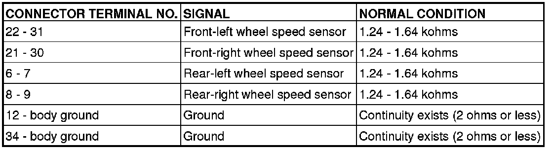
RESISTANCE AND CONTINUITY BETWEEN HARNESS-SIDE CONNECTOR TERMINALS
Required Special Tool:
MB991952: ABS Check Harness
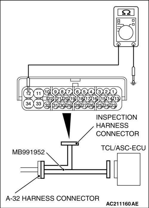
1. Disconnect the connector A-32, and connect the special tool ABS Check Harness (MB991952) to the wiring harness-side connector.
NOTE:
Do not connect the special tool ABS Check Harness (MB991952) to the TCL/ASC-ECU.
2. Measure the resistance and continuity between the terminals indicated in the table below.