Part 1
DIAGNOSTIC ITEM 10: Diagnose CAN bus lines thoroughly [Vehicles with multi-center display (middle-grade type or Mitsubishi Multi Communication System)]
CAUTION:
When servicing a CAN bus line, ground yourself by touching a metal object such as an unpainted water pipe. If you fail to do so, a component connected to the CAN bus line may be damaged.

TROUBLE JUDGMENT
If the M.U.T.-III cannot received signals from ECUs, CAN bus line connector(s) are broken or an open circuit has occurred.
COMMENTS ON TROUBLE SYMPTOM
The wiring harness wire or connectors may have loose, corroded, or damage terminals, or terminals pushed back in the connector, or an ECU may be defective.
TROUBLESHOOTING HINTS
- The wiring harness or connectors may have loose, corroded, or damage terminals, or terminals pushed back in the connector
- The ETACS-ECU may be defective
- The SRS-ECU may be defective
- The combination meter may be defective
- The A/C-ECU may be defective
- The G and yaw rate sensor may be defective
- The steering wheel sensor may be defective
- The TPMS receiver may be defective
- The multi-center display unit (middle-grade type or Mitsubishi Multi Communication System) may be defective
- The TCL/ASC-ECU may be defective
- The powertrain control module may be defective
DIAGNOSIS
Required Special Tools:
- MB991223: Harness Set
- MB992006: Extra Fine Probe
- MB991952: ABS Check Harness
- MB991923: Power Plant ECU Check Harness
- MB991958: Scan Tool (M.U.T.-III Sub Assembly)
- MB991824: V.C.I.
- MB991827: M.U.T.-III USB Cable
- MB991910: M.U.T.-III Main Harness A
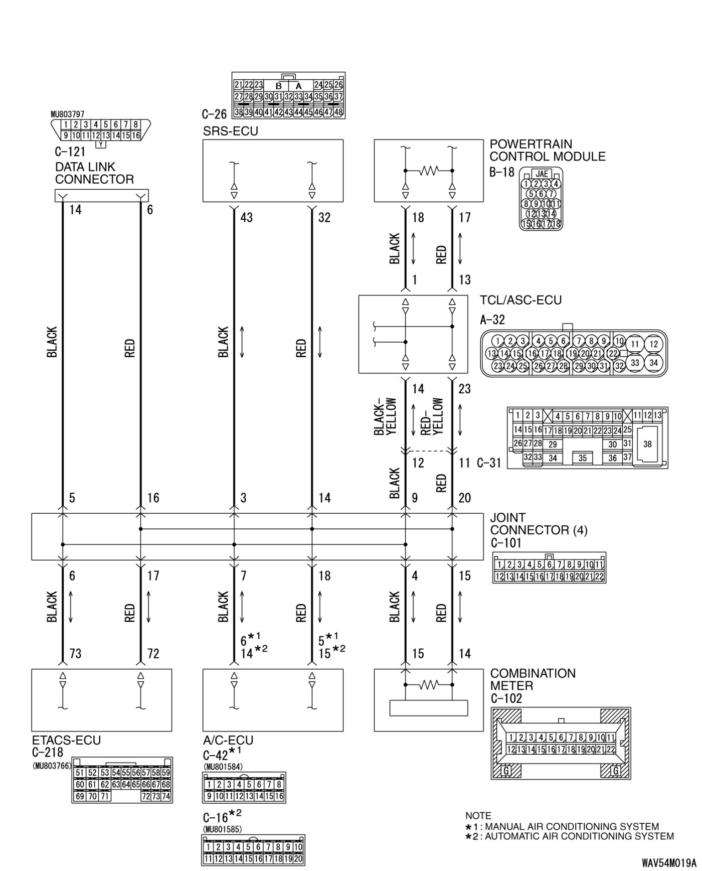
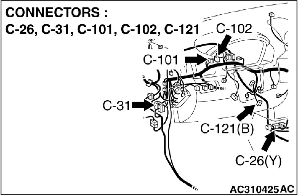
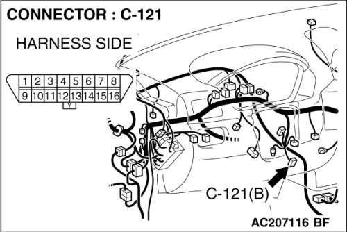
STEP 1. Check data link connector C-121 for loose, corroded or damaged terminals, or terminals pushed back in the connector.
CAUTION:
The strand end of the twist wire should be within 10 cm (4 inches) from the connector. For details refer to Precautions When CAN Bus Line(s) are Repaired.
Q. Is data link connector C-121 in good condition?
YES Go to Step 2 .
NO Repair the damaged parts.
STEP 2. Check the CAN bus lines at the data link connector. Measure the resistance at the data link connector C-121.
CAUTION:
A digital multimeter should be used. For details refer to Precautions When CAN Bus Line(s) are Repaired.
CAUTION:
The test wiring harness should be used. For details refer to Precautions When CAN Bus Line(s) are Repaired.
(1)Measure the resistance at the data link connector.
(2)Turn the ignition switch to the "LOCK" (OFF) position.
(3)
CAUTION:
Disconnect the negative battery terminal. For details refer to Precautions When CAN Bus Line(s) are Repaired.
Disconnect the negative battery terminal.
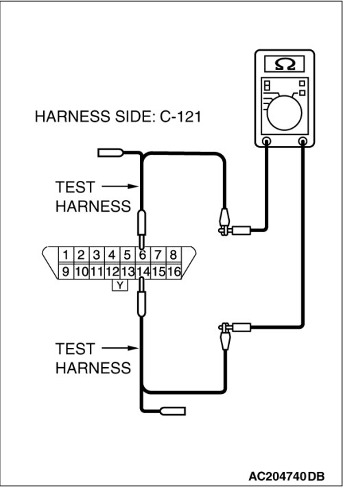
(4)Measure the resistance between data link connector terminals 6 and 14.
Q. How much resistance is measured?
2 ohms or less : Check the CAN_L and H lines for short circuit (Refer to Diagnostics Item 6).
No continuity : Diagnose terminator resistors at both ends (Refer to Diagnostics Item 7).
More than 2 ohms but continuity exists : Go to Step 3 .
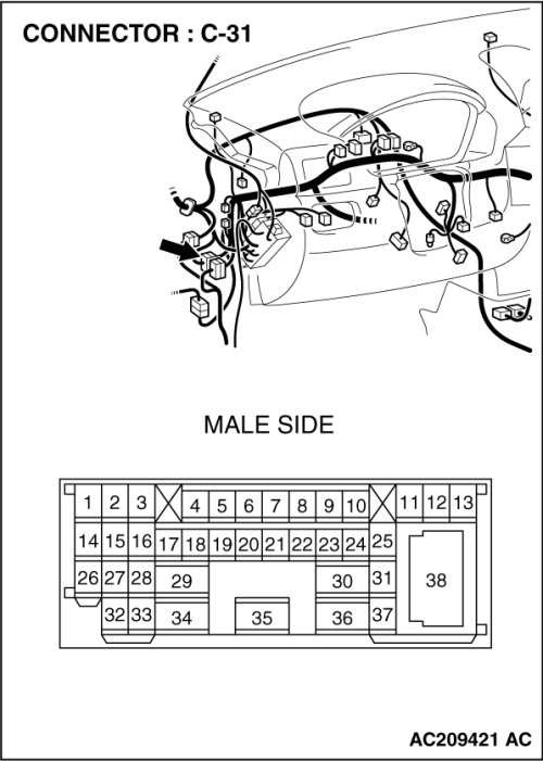
STEP 3. Check intermediate connector C-31 for loose, corroded or damaged terminals, or terminals pushed back in the connector.
CAUTION:
The strand end of the twist wire should be within 10 cm (4 inches) from the connector. For details refer to Precautions When CAN Bus Line(s) are Repaired.
Q. Is intermediate connector C-31 in good condition?
YES Go to Step 4 .
NO Repair the damaged parts.
STEP 4. Using scan tool MB991958, diagnose the CAN bus line (Disconnect intermediate connector C-31, and then determine that a failure is present at either the front wiring harness side or the instrument panel wiring harness side).
(1)Disconnect intermediate connector C-31.

(2)
CAUTION:
To prevent damage to scan tool MB991958, always turn the ignition switch to the "LOCK" (OFF) position before connecting or disconnecting scan tool MB991958.
Connect scan tool MB991958 to the data link connector.
(3)Turn the ignition switch to the "ON" position.
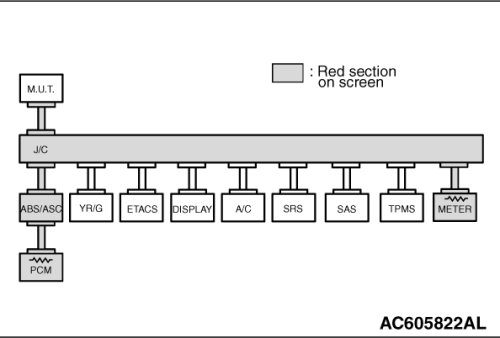
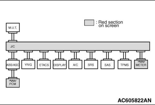
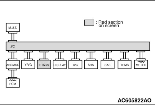
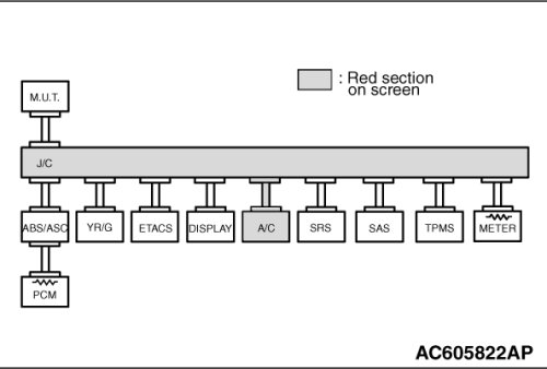
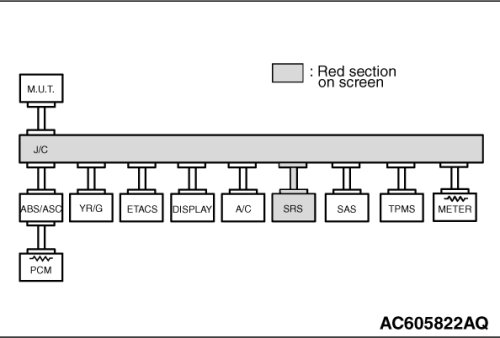
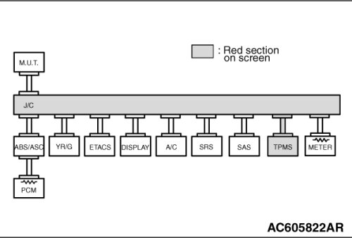
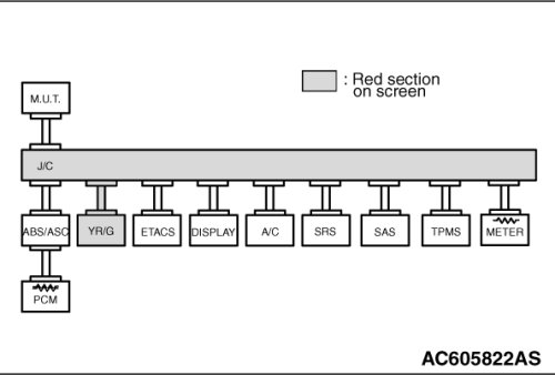
(4)Diagnose CAN bus lines, and check if the M.U.T.-III screen is as shown in the illustration.
(5)Turn the ignition switch to the "LOCK" (OFF) position.
(6)Connect intermediate connector C-31.
Q. Does the M.U.T.-III screen correspond to the illustration?
YES [The M.U.T.-III screen corresponds to the illustration] Go to Step 32 .
NO [The M.U.T.-III screen does not correspond to the illustration] Go to Step 5 .
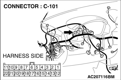
STEP 5. Check joint connector (4) C-101 and combination meter connector C-102 for loose, corroded or damaged terminals, or terminals pushed back in the connector.
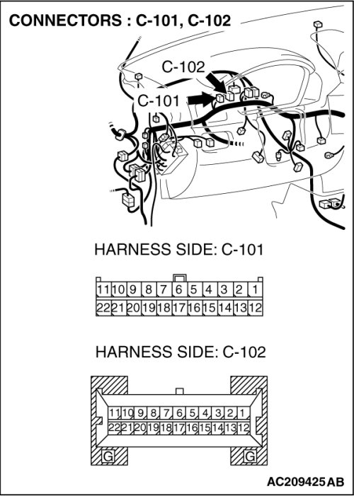
NOTE:
For the removal of the joint connector, refer to Service and Repair.
CAUTION:
The strand end of the twist wire should be within 10 cm (4 inches) from the connector. For details refer to Precautions When CAN Bus Line(s) are Repaired.
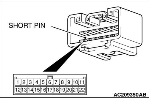
Check the joint connector at the wiring harness side for loose, corroded or damaged terminals, or terminals pushed back in the connector, and also check the short pin behind the connector for corrosion, deformation and delamination.
Q. Is joint connector (4) C-101 in good condition?
YES Go to Step 6 .
NO Repair the damaged parts. Replace the joint connector as necessary.
STEP 6. Using scan tool MB991958, diagnose the CAN bus line (Disconnect combination meter connector C-102, and check the combination meter system).
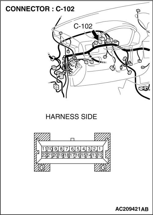
(1)Disconnect combination meter connector C-102.
(2)Turn the ignition switch to the "ON" position.
(3)Diagnose CAN bus lines, and check if the M.U.T.-III screen is as shown in the illustration.
(4)Turn the ignition switch to the "LOCK" (OFF) position.
(5)Disconnect combination meter connector C-102.
Q. Does the M.U.T.-III screen correspond to the illustration?
YES [The M.U.T.-III screen corresponds to the illustration] Go to Step 7 .
NO [The M.U.T.-III screen does not correspond to the illustration] Go to Step 8 .
STEP 7. Check the CAN bus lines between joint connector (4) and the combination meter. Measure the resistance between joint connector (4) C-101 and combination meter connector C-102.
CAUTION:
A digital multimeter should be used. For details refer to Precautions When CAN Bus Line(s) are Repaired.
CAUTION:
The test wiring harness should be used. For details refer to Precautions When CAN Bus Line(s) are Repaired.
(1)Disconnect joint connector (4) C-101 and combination meter connector C-102, and measure the resistance between each wiring harness side connector.
(2)Turn the ignition switch to the "LOCK" (OFF) position.
(3)
CAUTION:
Disconnect the negative battery terminal. For details refer to Precautions When CAN Bus Line(s) are Repaired.
Disconnect the negative battery terminal.
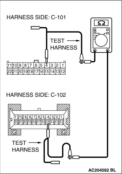
(4)Measure the resistance between joint connector (4) terminal 4 and combination meter connector terminal 15.
OK: 2 ohms or less
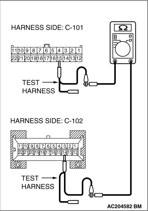
(5)Measure the resistance between joint connector (4) terminal 15 and combination meter connector terminal 14.
OK: 2 ohms or less
CAUTION:
Strictly observe the specified wiring harness repair procedure.
For details refer to Precautions on How to Repair the CAN Bus Line(s).
Q. Do all the resistances measure 2 ohms or less?
YES [All the resistances measure 2 ohms or less] Power supply to the combination meter may be suspected. Diagnose the combination meter by referring to Combination meter assembly Inspection Procedure 1.
NO [If either of the resistances measures more than 2 ohms or all the resistances measure more than 2 ohms] Repair the wiring harness between joint connector (4) and the combination meter connector.
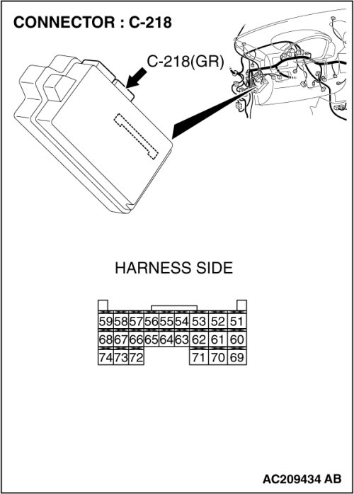
STEP 8. Check ETACS-ECU connector C-218 for loose, corroded or damaged terminals, or terminals pushed back in the connector.
CAUTION:
The strand end of the twist wire should be within 10 cm (4 inches) from the connector. For details refer to Precautions When CAN Bus Line(s) are Repaired.
Q. Is ETACS-ECU connector C-218 in good condition?
YES Go to Step 9 .
NO Repair the damaged parts.
STEP 9. Using scan tool MB991958, diagnose the CAN bus line (Disconnect ETACS-ECU connector C-218, and check the ETACS-ECU system).
(1)Disconnect ETACS-ECU connector C-218.
(2)Turn the ignition switch to the "ON" position.
(3)Diagnose CAN bus lines, and check if the M.U.T.-III screen is as shown in the illustration.
(4)Turn the ignition switch to the "LOCK" (OFF) position.
(5)Connect ETACS-ECU connector C-218.
Q. Does the M.U.T.-III screen correspond to the illustration?
YES [The M.U.T.-III screen corresponds to the illustration] Go to Step 10 .
NO [The M.U.T.-III screen does not correspond to the illustration] Go to Step 11 .
STEP 10. Check the CAN bus lines between joint connector (4) and the ETACS-ECU. Measure the resistance between joint connector (4) C-101 and ETACS-ECU connector C-218.
CAUTION:
A digital multimeter should be used. For details refer to Precautions When CAN Bus Line(s) are Repaired.
CAUTION:
The test wiring harness should be used. For details refer to Precautions When CAN Bus Line(s) are Repaired.
(1)Disconnect joint connector (4) C-101 and ETACS-ECU connector C-218, and measure the resistances at the wiring harness sides of joint connector (4) C-101 and ETACS-ECU connector C-218.
(2)Turn the ignition switch to the "LOCK" (OFF) position.
(3)
CAUTION:
Disconnect the negative battery terminal. For details refer to Precautions When CAN Bus Line(s) are Repaired.
Disconnect the negative battery terminal.
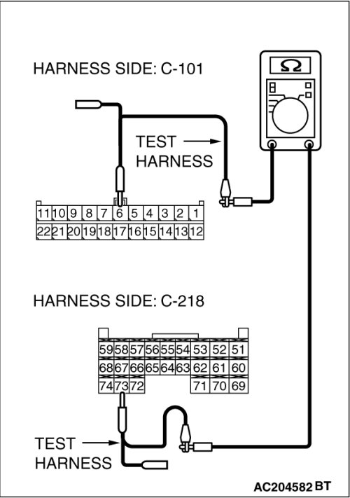
(4)Measure the resistance between joint connector (4) terminal 6 and ETACS-ECU connector terminal 73.
OK: 2 ohms or less
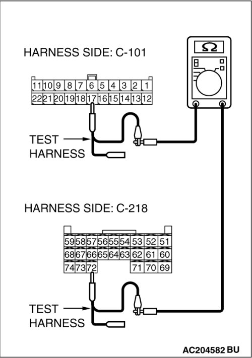
(5)Measure the resistance between joint connector (4) terminal 17 and ETACS-ECU connector terminal 72.
OK: 2 ohms or less
CAUTION:
Strictly observe the specified wiring harness repair procedure.
For details refer to Precautions on How to Repair the CAN Bus Line(s).
Q. Do all the resistances measure 2 ohms or less?
YES [All the resistances measure 2 ohms or less] Power supply to the ETACS-ECU may be suspected. Diagnose the ETACS-ECU by referring to Diagnosis Inspection Procedure A-3.
NO [If either of the resistances measures more than 2 ohms or all the resistances measure more than 2 ohms] Repair the wiring harness between joint connector (4) and the ETACS-ECU connector.
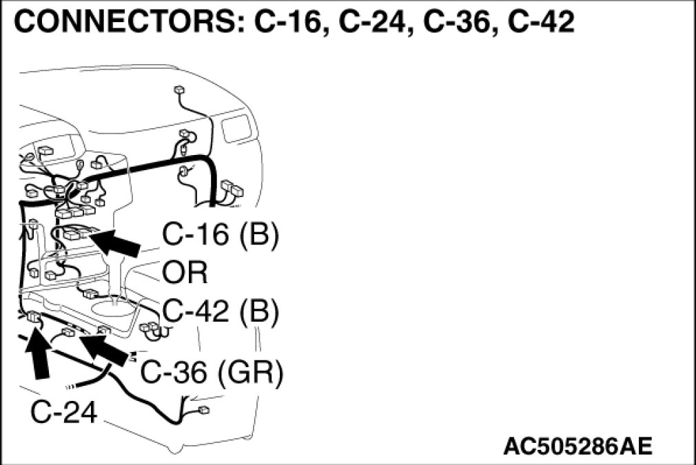
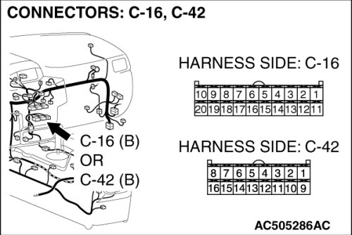
STEP 11. Check A/C-ECU connector C-42 [manual air conditioning system] or A/C-ECU connector C-16 [automatic air conditioning system] for loose, corroded or damaged terminals, or terminals pushed back in the connector.
CAUTION:
The strand end of the twist wire should be within 10 cm (4 inches) from the connector. For details refer to Precautions When CAN Bus Line(s) are Repaired.
Q. Is A/C-ECU connector C-42[ manual air conditioning system] or A/C-ECU connector C-16[ automatic air conditioning system] C-16 in good condition?
YES Go to Step 12 .
NO Repair the damaged parts.
STEP 12. Using scan tool MB991958, diagnose the CAN bus line (Disconnect A/C-ECU connector C-42 [manual air conditioning system] or A/C-ECU connector C-16 [automatic air conditioning system], and check the A/C-ECU system).
(1)Disconnect A/C-ECU connector C-42 [manual air conditioning system] or A/C-ECU connector C-16 [automatic air conditioning system].
(2)Turn the ignition switch to the "ON" position.
(3)Diagnose CAN bus lines, and check if the M.U.T.-III screen is as shown in the illustration.
(4)Turn the ignition switch to the "LOCK" (OFF) position.
(5)Connect A/C-ECU connector C-42 [manual air conditioning system] or A/C-ECU connector C-16 [automatic air conditioning system].
Q. Does the M.U.T.-III screen correspond to the illustration?
YES [The M.U.T.-III screen corresponds to the illustration] Go to Step 13 .
NO [The M.U.T.-III screen does not correspond to the illustration] Go to Step 14 .
STEP 13. Check the CAN bus lines between joint connector (4) and the A/C-ECU. Measure the resistance between joint connector (4) C-101 and A/C-ECU connector C-42 [manual air conditioning system] or A/C-ECU connector C-16 [automatic air conditioning system].
CAUTION:
A digital multimeter should be used. For details refer to Precautions When CAN Bus Line(s) are Repaired.
CAUTION:
The test wiring harness should be used. For details refer to Precautions When CAN Bus Line(s) are Repaired.
(1)Disconnect joint connector (4) C-101 and A/C-ECU connector C-42 [manual air conditioning system] or A/C-ECU connector C-16 [automatic air conditioning system], and measure the resistances at the wiring harness sides of joint connector (4) C-101 and A/C-ECU connector C-42 [manual air conditioning system] or A/C-ECU connector C-16 [automatic air conditioning system].
(2)Turn the ignition switch to the "LOCK" (OFF) position.
(3)
CAUTION:
Disconnect the negative battery terminal. For details refer to Precautions When CAN Bus Line(s) are Repaired.
Disconnect the negative battery terminal.
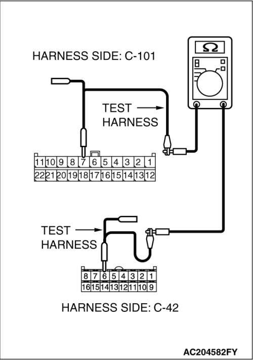
(4)Measure the resistance between joint connector (4) terminal 7 and A/C-ECU connector C-42 [manual air conditioning system] terminal 6.
OK: 2 ohms or less
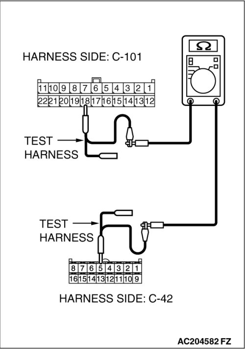
(5)Measure the resistance between joint connector (4) terminal 18 and A/C-ECU connector C-42 [manual air conditioning system] terminal 5.
OK: 2 ohms or less
CAUTION:
Strictly observe the specified wiring harness repair procedure.
For details refer to Precautions on How to Repair the CAN Bus Line(s).
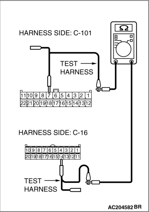
(6)Measure the resistance between joint connector (4) terminal 7 and A/C-ECU connector C-16 [automatic air conditioning system] terminal 14.
OK: 2 ohms or less
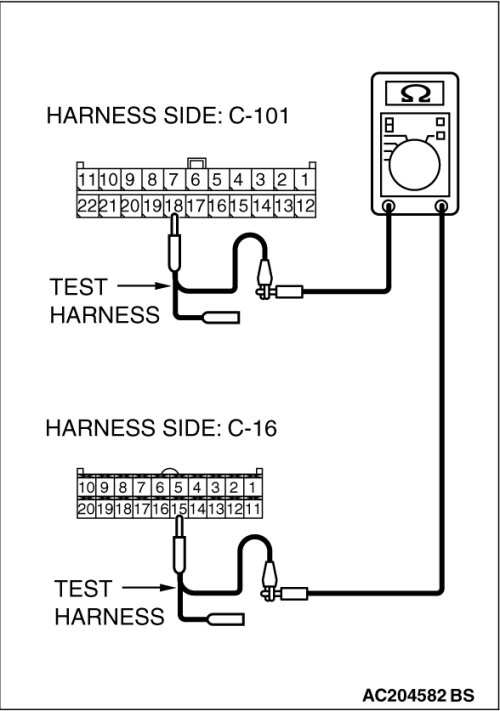
(7)Measure the resistance between joint connector (4) terminal 18 and A/C-ECU connector C-16 [automatic air conditioning system] terminal 15.
OK: 2 ohms or less
CAUTION:
Strictly observe the specified wiring harness repair procedure.
For details refer to Precautions on How to Repair the CAN Bus Line(s).
Q. Do all the resistances measure 2 ohms or less?
YES [All the resistances measure 2 ohms or less] Power supply to the A/C-ECU may be suspected. Diagnose the air conditioning system. Inspection Procedure 2.
NO [If either of the resistances measures more than 2 ohms or all the resistances measure more than 2 ohms] Repair the wiring harness between joint connector (4) and the A/C-ECU connector.
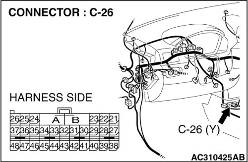
STEP 14. Check SRS-ECU connector C-26 for loose, corroded or damaged terminals, or terminals pushed back in the connector.
CAUTION:
The strand end of the twist wire should be within 10 cm (4 inches) from the connector. For details refer to Precautions When CAN Bus Line(s) are Repaired.
Q. Is SRS-ECU connector C-26 in good condition?
YES Go to Step 15 .
NO Repair the damaged parts.
STEP 15. Using scan tool MB991958, diagnose the CAN bus line (Disconnect SRS-ECU connector C-26, and check the SRS-ECU system).
(1)Disconnect SRS-ECU connector C-26.
(2)Turn the ignition switch to the "ON" position.
(3)Diagnose CAN bus lines, and check if the M.U.T.-III screen is as shown in the illustration.
(4)Turn the ignition switch to the "LOCK" (OFF) position.
(5)Connect SRS-ECU connector C-26.
Q. Does the M.U.T.-III screen correspond to the illustration?
YES [The M.U.T.-III screen corresponds to the illustration] Go to Step 16 .
NO [The M.U.T.-III screen does not correspond to the illustration] Go to Step 17 .
STEP 16. Check the CAN bus lines between joint connector (4) and the SRS-ECU. Measure the resistance between joint connector (4) C-101 and SRS-ECU connector C-26.
CAUTION:
A digital multimeter should be used. For details refer to Precautions When CAN Bus Line(s) are Repaired.
CAUTION:
The test wiring harness should be used. For details refer to Precautions When CAN Bus Line(s) are Repaired.
(1)Disconnect joint connector (4) C-101 and SRS-ECU connector C-26, and measure the resistances at the wiring harness sides of joint connector (4) C-101 and SRS-ECU connector C-26.
(2)Turn the ignition switch to the "LOCK" (OFF) position.
(3)
CAUTION:
Disconnect the negative battery terminal. For details refer to Precautions When CAN Bus Line(s) are Repaired.
Disconnect the negative battery terminal.
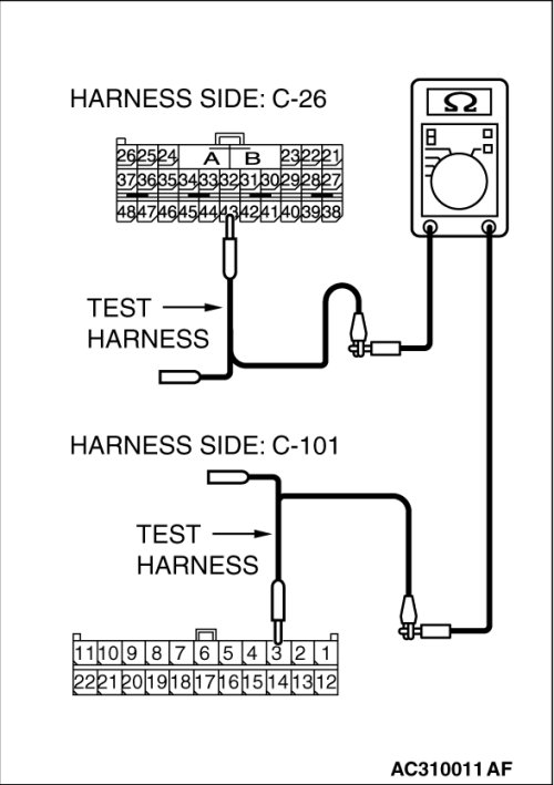
(4)Measure the resistance between joint connector (4) terminal 3 and SRS-ECU connector terminal 43.
OK: 2 ohms or less
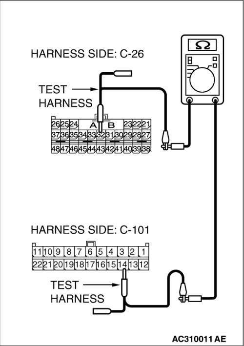
(5)Measure the resistance between joint connector (4) terminal 14 and SRS-ECU connector terminal 32.
OK: 2 ohms or less
CAUTION:
Strictly observe the specified wiring harness repair procedure.
For details refer to Precautions on How to Repair the CAN Bus Line(s).
Q. Do all the resistances measure 2 ohms or less?
YES : [All the resistances measure 2 ohms or less] Power supply to the SRS-ECU may be suspected. Diagnose the SRS by referring to SRS air bag diagnosis Introduction.
NO [If either of the resistances measures more than 2 ohms or all the resistances measure more than 2 ohms] Repair the wiring harness between joint connector (4) and the SRS-ECU connector.
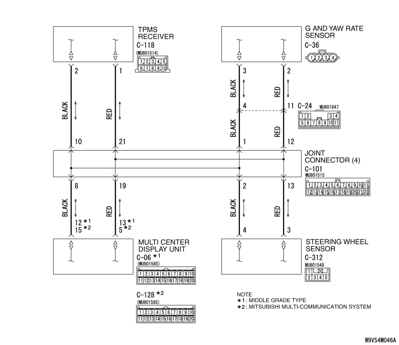
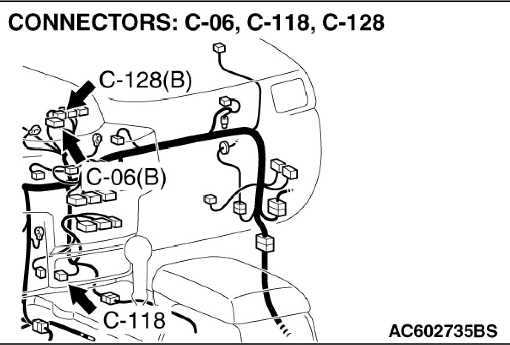
STEP 17. Check TPMS receiver connector C-118 for loose, corroded or damaged terminals, or terminals pushed back in the connector.
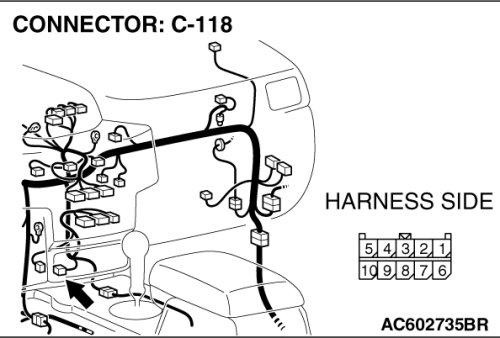
CAUTION:
The strand end of the twisted wire should be within 10 cm (4 inches) from the connector.
For details refer to Precautions When CAN Bus Line(s) are Repaired.
Q. Is TPMS receiver connector C-118 in good condition?
YES Go to Step 18.
NO Repair the damaged parts.
STEP 18. Using scan tool MB991958, diagnose the CAN bus line (Disconnect TPMS receiver connector C-118, and check the supplemental restraint system).
(1)Disconnect TPMS receiver connector C-118.
(2)Turn the ignition switch to the "ON" position.
(3)Diagnose CAN bus lines, and check if the M.U.T.-III screen is as shown in the illustration.
(4)Turn the ignition switch to the "LOCK" (OFF) position.
(5)Connect the TPMS receiver connector C-118.
Q. Does the M.U.T.-III screen correspond to the illustration?
YES : If the M.U.T.-III screen corresponds to the illustration, go to Step 19 .
NO : If the M.U.T.-III screen does not correspond to the illustration, go to Step 20
.
STEP 19. Check the CAN bus lines between joint connector (4) and the TPMS receiver. Measure the resistance between joint connector (4) C-101 and TPMS receiver connector C-118.
CAUTION:
A digital multimeter should be used. For details refer to Precautions When CAN Bus Line(s) are Repaired.
CAUTION:
The test wiring harness should be used. For details refer to Precautions When CAN Bus Line(s) are Repaired.
(1)Disconnect joint connector (4) C-101 and TPMS receiver connector C-118, and measure the resistances at the wiring harness sides of joint connector (4) C-101 and TPMS receiver connector C-118.
(2)Turn the ignition switch to the "LOCK" (OFF) position.
(3)
CAUTION:
Disconnect the negative battery terminal. For details refer to Precautions When CAN Bus Line(s) are Repaired.
Disconnect the negative battery terminal.
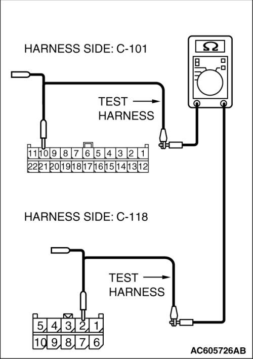
(4)Measure the resistance between joint connector (4) terminal 10 and TPMS receiver connector terminal 2.
OK: 2 ohms or less
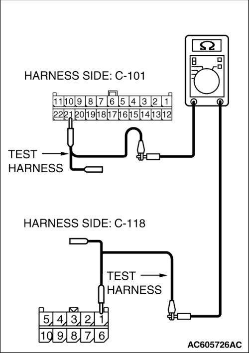
(5)Measure the resistance between joint connector (4) terminal 21 and TPMS receiver connector terminal 1.
OK: 2 ohms or less
CAUTION:
Strictly observe the specified wiring harness repair procedure.
For details refer to Precautions on How to Repair the CAN Bus Line(s).
Q. Do all the resistances measure 2 ohms or less?
YES If all the resistances measure 2 ohms or less, power supply to the TPMS receiver may be suspected. Diagnose the supplemental restraint system. Introduction.
NO If either of the resistances measures more than 2 ohms or all the resistances measure more than 2 ohms, repair the wiring harness between joint connector (4) and the TPMS receiver connector.
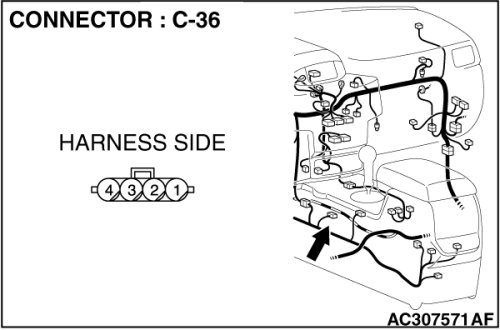
STEP 20. Check G and yaw rate sensor connector C-36 for loose, corroded or damaged terminals, or terminals pushed back in the connector.
CAUTION:
The strand end of the twist wire should be within 10 cm (4 inches) from the connector. For details refer to Precautions When CAN Bus Line(s) are Repaired.
Q. Is G and yaw rate sensor connector C-36 in good condition?
YES Go to Step 21 .
NO Repair the damaged parts.
STEP 21. Using scan tool MB991958, diagnose the CAN bus line (Disconnect G and yaw rate sensor connector C-36, and check the G and yaw rate sensor system).
(1)Disconnect G and yaw rate sensor connector C-36.
(2)Turn the ignition switch to the "ON" position.
(3)Diagnose CAN bus lines, and check if the M.U.T.-III screen is as shown in the illustration.
(4)Turn the ignition switch to the "LOCK" (OFF) position.
(5)Connect G and yaw rate sensor connector C-36.
Q. Does the M.U.T.-III screen correspond to the illustration?
YES [The M.U.T.-III screen corresponds to the illustration] Go to Step 22 .
NO [The M.U.T.-III screen does not correspond to the illustration] Go to Step 25 .
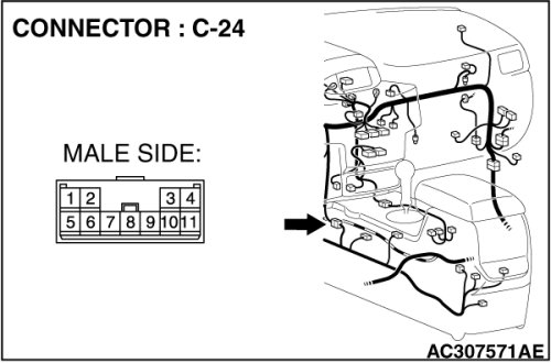
STEP 22. Check intermediate connector C-24 for loose, corroded or damaged terminals, or terminals pushed back in the connector.
CAUTION:
The strand end of the twist wire should be within 10 cm (4 inches) from the connector. For details refer to Precautions When CAN Bus Line(s) are Repaired.
Q. Is intermediate connector C-24 in good condition?