Diagnostics Item 17
DIAGNOSTIC ITEM 17: Diagnose the lines between CAN main bus line and the G and yaw rate sensor
CAUTION:
When servicing a CAN bus line, ground yourself by touching a metal object such as an unpainted water pipe. If you fail to do so, a component connected to the CAN bus line may be damaged.
TROUBLE JUDGMENT
If the M.U.T.-III cannot received signals from the G and yaw rate sensor, CAN bus line connector(s) are broken or an open circuit has occurred.
COMMENTS ON TROUBLE SYMPTOM
The wiring harness wire or connectors may have loose, corroded, or damage terminals, or terminals pushed back in the connector, or the G and yaw rate sensor may be defective.
TROUBLESHOOTING HINTS
- The wiring harness or connectors may have loose, corroded, or damage terminals, or terminals pushed back in the connector
- The G and yaw rate sensor may be defective
DIAGNOSIS
Required Special Tools:
- MB991223: Harness Set
- MB992006: Extra Fine Probe
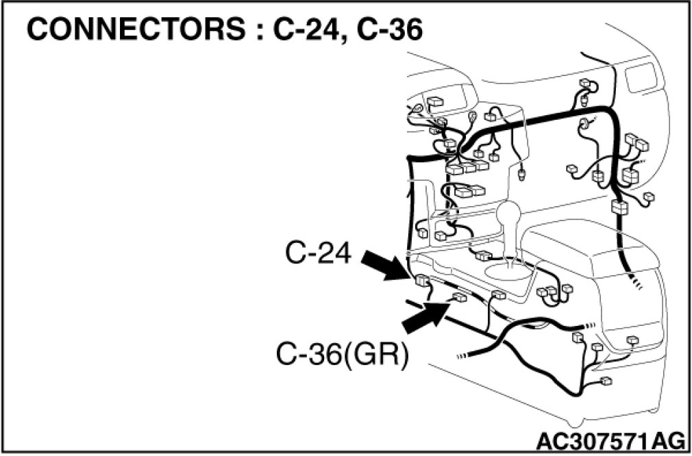
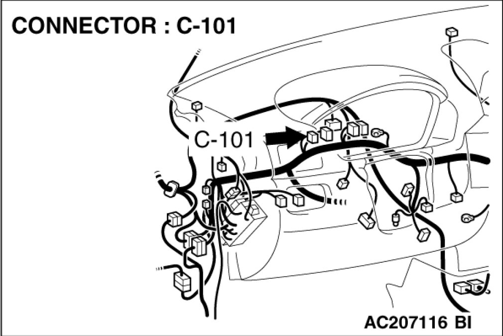
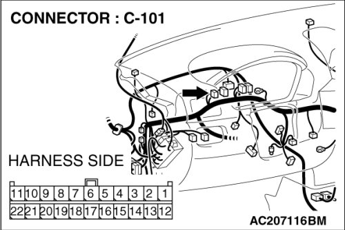
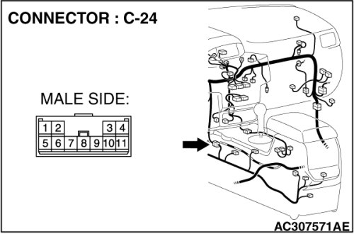
STEP 1. Check intermediate connector C-24, joint connector (4) C-101 and G and yaw rate sensor connector C-36 for loose, corroded or damaged terminals, or terminals pushed back in the connector.
NOTE:
For the removal of the joint connector, refer to Service and Repair.
CAUTION:
The strand end of the twist wire should be within 10 cm (4 inches) from the connector. For details refer to Precautions When CAN Bus Line(s) are Repaired.
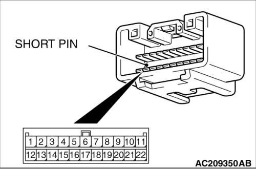
Check the joint connector at the wiring harness side for loose, corroded or damaged terminals, or terminals pushed back in the connector, and also check the short pin behind the connector for corrosion, deformation and delamination.
Q. Are intermediate connector C-24, joint connector (4) C-101 and G and yaw rate sensor connector C-36 in good condition?
YES Go to Step 2 .
NO Repair the damaged parts. Replace the joint connector as necessary.
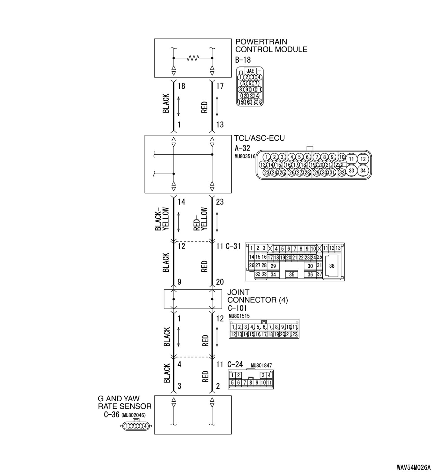
STEP 2. Check the CAN bus lines between intermediate connector C-24 and the G and yaw rate sensor. Measure the resistance between intermediate connector C-24 and g and yaw rate sensor connector C-36.
CAUTION:
A digital multimeter should be used. For details refer to Precautions When CAN Bus Line(s) are Repaired.
CAUTION:
The test wiring harness should be used. For details refer to Precautions When CAN Bus Line(s) are Repaired.
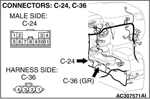
(1)Disconnect intermediate connector C-24 and G and yaw rate sensor connector C-36, and measure the resistance between the wiring harness side connector of G and yaw rate sensor connector C-36 and the male side connector of intermediate connector C-24 (at front wiring harness side).
(2)Turn the ignition switch to the "LOCK" (OFF) position.
(3)
CAUTION:
Disconnect the negative battery terminal. For details refer to Precautions When CAN Bus Line(s) are Repaired.
Disconnect the negative battery terminal.
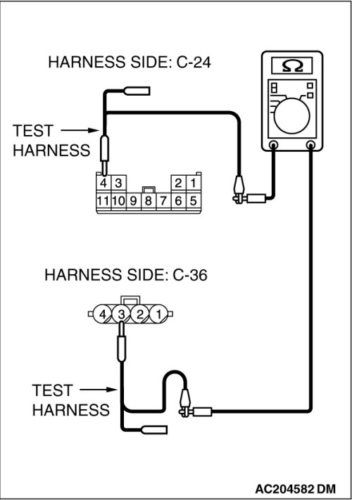
(4)Measure the resistance between intermediate connector terminal 4 and G and yaw rate sensor connector terminal 3.
OK: 2 ohms or less
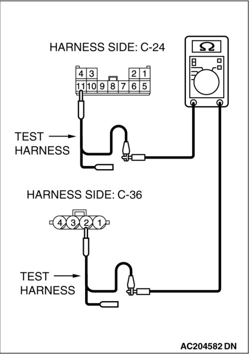
(5)Measure the resistance between intermediate connector terminal 11 and G and yaw rate sensor connector terminal 2.
OK: 2 ohms or less
CAUTION:
Strictly observe the specified wiring harness repair procedure.
For details refer to Precautions on How to Repair the CAN Bus Line(s).
Q. Do all the resistances measure 2 ohms or less?
YES [All the resistances measure 2 ohms or less] Go to Step 3 .
NO [If either of the resistances measures more than 2 ohms or all the resistances measure more than 2 ohms] Repair the wiring harness between intermediate connector C-24 and the G and yaw rate sensor connector.
STEP 3. Check the CAN bus lines between intermediate connector C-24 and the joint connector (4). Measure the resistance between intermediate connector C-24 and joint connector (4) C-101.
CAUTION:
A digital multimeter should be used. For details refer to Precautions When CAN Bus Line(s) are Repaired.
CAUTION:
The test wiring harness should be used. For details refer to Precautions When CAN Bus Line(s) are Repaired.
(1)Disconnect joint connector (4) C-101 and intermediate connector C-24, and measure the resistance between the wiring harness side connector of joint connector (4) C-101 and the female side connector of intermediate connector C-24 (instrument panel wiring harness side).
(2)Turn the ignition switch to the "LOCK" (OFF) position.
(3)
CAUTION:
Disconnect the negative battery terminal. For details refer to Precautions When CAN Bus Line(s) are Repaired.
Disconnect the negative battery terminal.
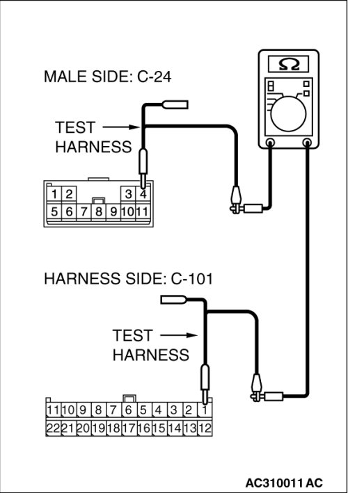
(4)Measure the resistance between joint connector (4) terminal 1 and intermediate connector terminal 4.
OK: 2 ohms or less
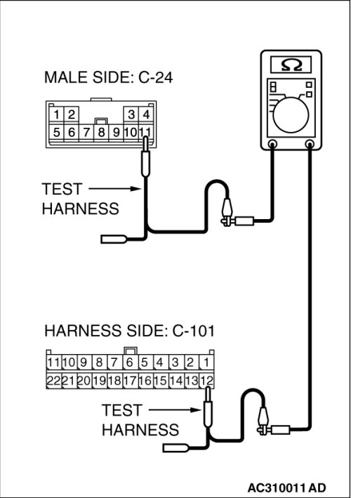
(5)Measure the resistance between joint connector (4) terminal 12 and intermediate connector terminal 11.
OK: 2 ohms or less
CAUTION:
Strictly observe the specified wiring harness repair procedure.
For details refer to Precautions on How to Repair the CAN Bus Line(s).
Q. Do all the resistances measure 2 ohms or less?
YES [All the resistances measure 2 ohms or less] Power supply to the G and yaw rate sensor may be suspected. Diagnose the ASC system. Inspection Procedure 5.
NO [If either of the resistances measures more than 2 ohms or all the resistances measure more than 2 ohms] Repair the wiring harness wires between intermediate connector C-24 and joint connector (4).