Inspection & Adjustment
Correct front wheel alignment is necessary to provide proper handling and to prevent uneven tire wear. To ensure correct alignment, angles should be checked, and if necessary corrected, in the following sequence: caster and kingpin inclination, camber, toe-setting, and the turning angle and toe-out on turns. Front wheel alignment should only be checked after ensuring that the rear wheels are properly aligned in relation to the vehicle centerline, as most equipment uses the rear wheels as reference for correct front wheel alignment. Front wheel alignment should be checked with the vehicle unladen, at normal ride height, and following equipment manufacturer's instructions.
CASTER & KINGPIN INCLINATION
Kingpin inclination is a function of the steering knuckle design and cannot be adjusted. Caster, the alignment angle which provides the self-centering steering effect, is only adjustable on truck models which do not use strut-type front suspensions. If caster or kingpin angle are not within specifications on models with strut-type front suspension, check suspension components and sheet metal for damage, distortion and excessive wear, and repair as needed. For caster adjustment On Pathfinder, Pickup and Van, refer to camber adjustment, as the caster and camber are both adjusted by inserting shims between the upper control arm spindle and the crossmember.
CAMBER
On these models, caster and camber are adjusted together by varying the thickness of shims between the upper control arm shaft and crossmember. To check and adjust caster and camber, proceed as follows:
1. Prior to checking and adjusting caster and camber, ensure that front suspension height is within specifications as follows:
Fig. 1 Front Suspension Height Measurement. 2WD:
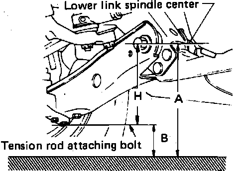
Fig. 2 Front Suspension Height Measurement. 4WD:
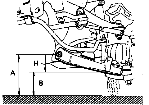
a. Measure suspension height of suspension arm pivot (A) and height of tension rod attaching bolt or steering stopper bracket (B), Figs. 8 and 9.
Fig. 10 Suspension height specifications. Pathfinder & Pickup:
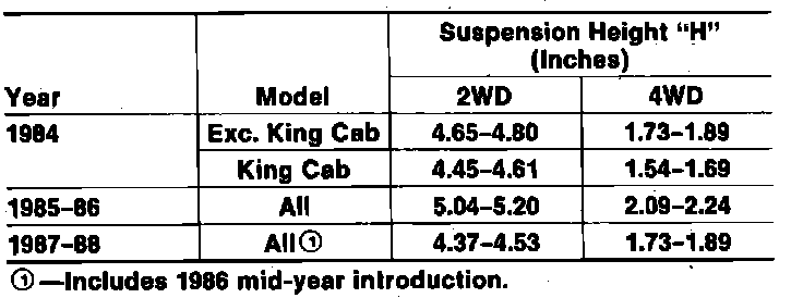
b. Subtract measurement (B) from measurement (A) to determine suspension height (H), Figs. 8 and 9, and compare remainder to specifications shown in chart, Fig. 10.
c. If unladen vehicle height is not within specifications, jounce vehicle several times to settle suspension. If height is still not within specifications, check suspension and repair or replace component as needed before continuing with alignment procedure.
2. Check caster and camber and refer to wheel alignment specifications.
3. If caster and or camber are not within specifications, place suitable jack under lower control arm, raise arm to remove tension from upper control arm and loosen nuts securing upper control arm to crossmember.
4. Replace shims between upper control arm shaft and crossmember, noting the following:
a. Do not use more than 3 shims at any one position, and ensure that shim thickness does not exceed .236 inch (6 mm) on 1982-84 all and 1985-86 2WD models, or .315 inch (8 mm) on 1985-86 4WD models and all 1987-88 models.
b. When installing shims with a right angle tab at the top, ensure tab faces control arm shaft, insert shim from bracket side and only use one shim of this type at any one position.
c. To adjust caster, vary thickness of shims between front and rear positions. When thickness of front shim is increased, caster decreases. When increasing shim thickness at the rear position, caster increases. When performing adjustment, ensure that difference in shim thickness between front and rear positions does not exceed .079 inch (2 mm). Camber angle is affected by varying shim thickness to perform caster adjustment. Always adjust caster angle first, then reduce or increase shim thickness equally at front and rear positions to adjust camber.
d. To adjust camber, add shims of equal thickness to both front and rear positions to move camber toward a more positive value, or decrease shim thickness equally at front and rear positions to move camber toward a more negative value.
5. Tighten upper control arm nuts and ensure caster and camber are still within specifications.
Fig. 1 Measuring Toe-in:

TOE SETTING
The toe setting is the measurement of the wheels in relation to the vehicle centerline, Fig. 1. The leading edge of each wheel should toe-in or toe-out slightly in relation to the vehicle centerline to ensure proper vehicle tracking. Toe should be inspected using suitable alignment gauges, following manufacturer's instructions. When checking or adjusting toe, always ensure that the setting of the left and right wheels is as nearly equal as possible.
Fig. 3 Typical Tie Rod Length Measurement:
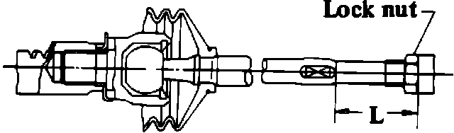
Fig. 17 Tie rod length specifications:
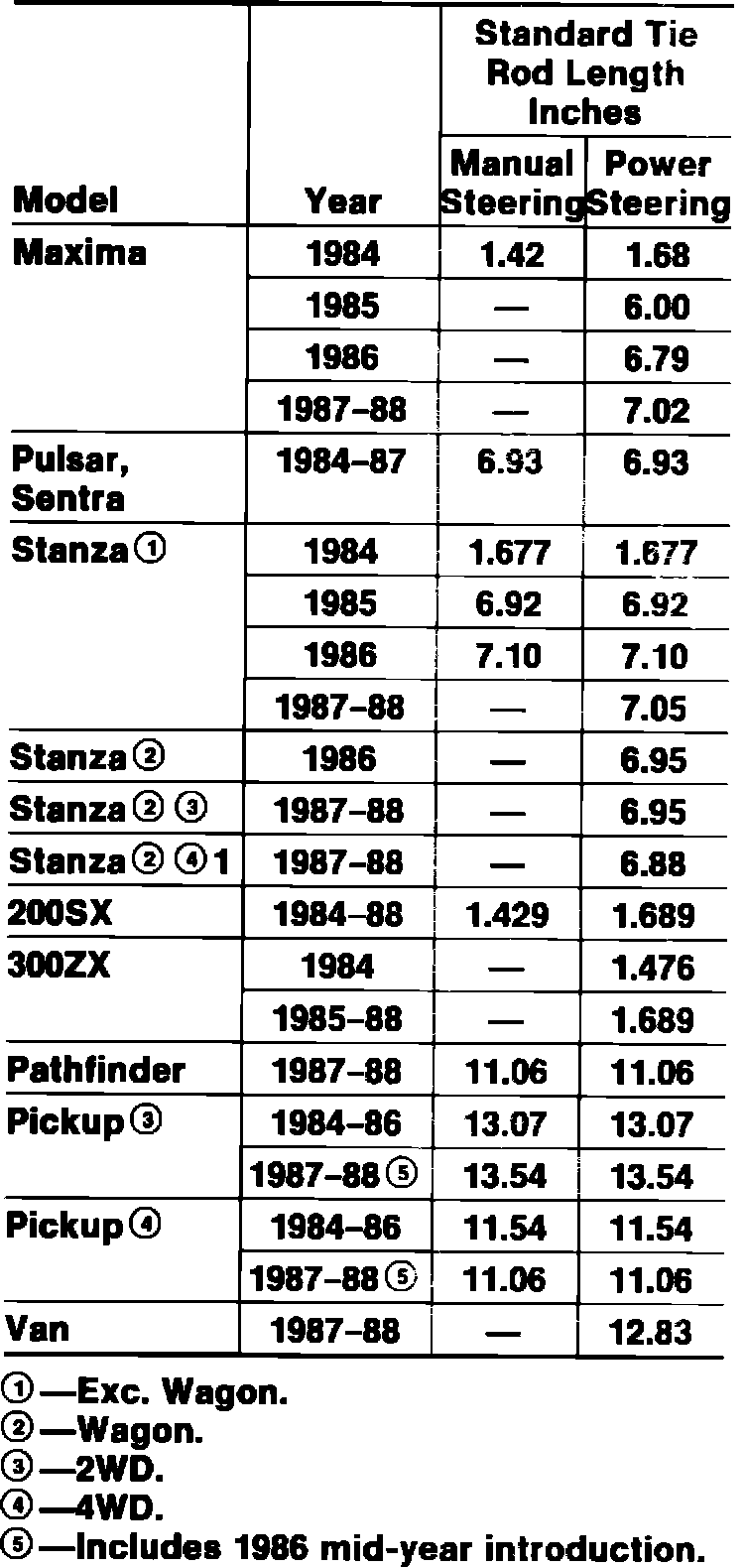
Toe is adjusted by loosening the tie rod locknuts or adjusting sleeve bolts and equally altering the length of the tie rods. After toe has been adjusted to specifications, the lengths of the left and right tie rods, Fig. 16, should be nearly equal and close to the length specified in Fig. 17. If tie rod lengths are incorrect, tie rods should be disassembled and adjusted to specifications, and the toe setting should be readjusted before checking steering angles. Incorrect tie rod length will adversely affect steering angles and toe-out on turns.
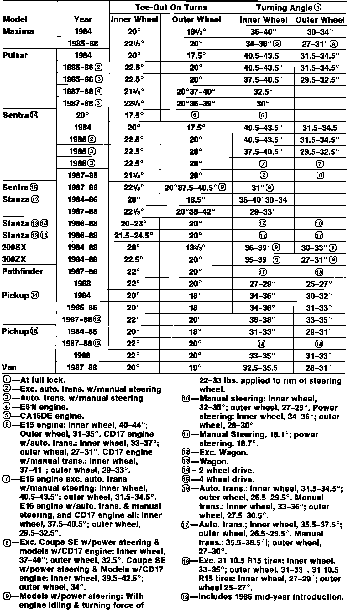
Fig. 18 Turning angle specifications:
STEERING ANGLE
When a vehicle negotiates a turn, the inner wheel must turn at a sharper angle than the outer wheel, and the outer wheel must travel farther than the inner wheel. Vehicle steering geometry is calculated to allow for these variations, causing the outer wheel to to-out by a calibrated amount. This toe-out on turns is also referred to as steering angle and on these models, is generally checked at two positions. The first position is at a reference point on the inner wheel travel while the second position of measurement is at full steering lock. To check steering angles, proceed as follows:
1. Place unladen vehicle on suitable alignment rack and ensure that kingpin angle, caster, camber and toe settings are within specifications.
2. Turn wheels from straight-ahead position until the inner wheel is at the position specified for ``Toe-Out On Turns'' shown in Fig. 18. If the outer wheel reference angle is incorrect, check for damaged or improperly adjusted tie rods. Perform check in both left and right directions.
3. On models less rack and pinion steering, proceed as follows:
a. Rotate steering to full lock in each direction.
b. Adjust inner wheel ``Turning Angle'' to value specified in Fig. 18, by adjusting position of steering stop.
c. With inner wheel adjusted to specifications, outer wheel turning angle should be as specified in Fig. 18. If outer wheel turning angle is incorrect, repair or replace steering linkage as needed.
4. On models with rack and pinion steering, proceed as follows:
a. Turn steering to full lock and measure inner and outer wheel turning angles.
b. If ``Turning Angles'' at full lock are not within specifications, Fig. 18, check for damaged steering linkage or improperly adjusted tie rods.
c. If steering linkage and tie rods are satisfactory, check for improper rack or rack piston stroke and repair steering gear as needed.