Related Diagnostic Procedures
Ignition Coil And Power Transistor:
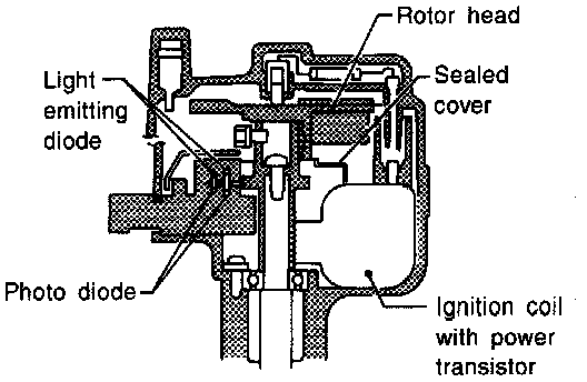
COMPONENT DESCRIPTION
The ignition signal from the ECM is sent to the power transistor. The power transistor switches on and off the ignition coil primary circuit. As the primary circuit is turned on and off, the proper high voltage is induced in the coil secondary circuit.
Diagnostic Procedure:
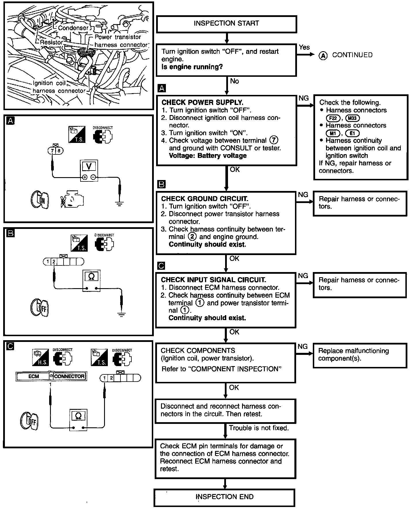
Diagnostic Procedure:
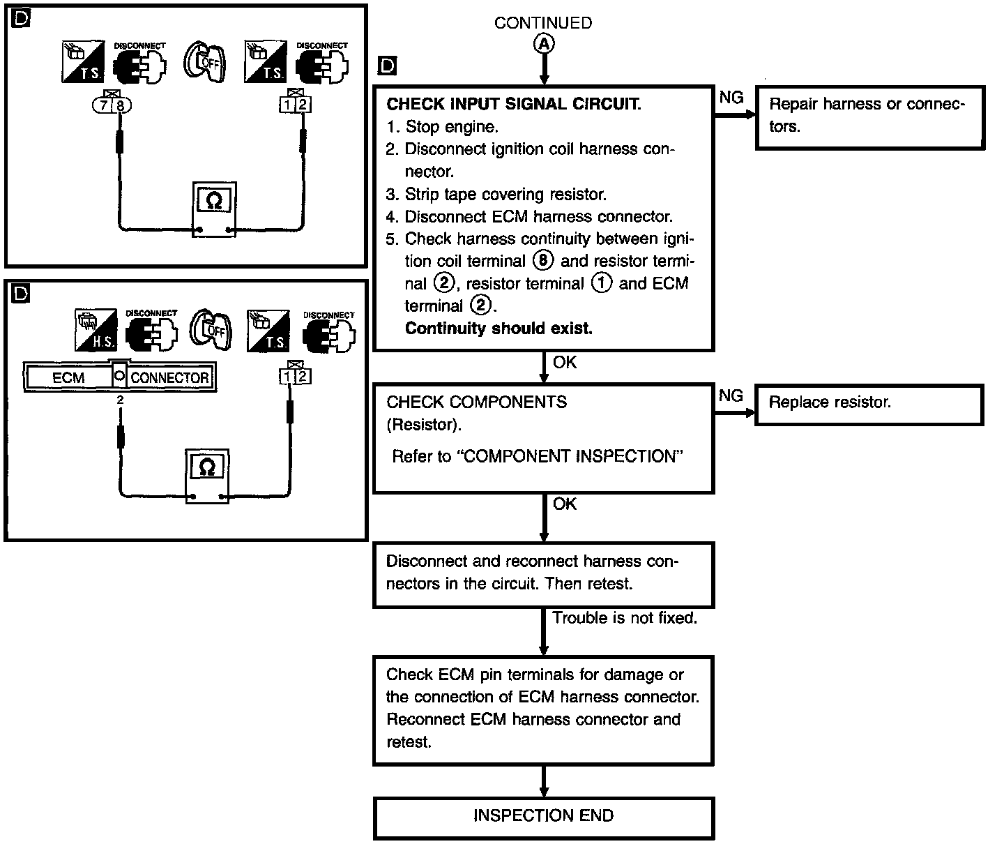
DIAGNOSTIC PROCEDURE
Ignition Signal (DTC: 0201) Diagram:
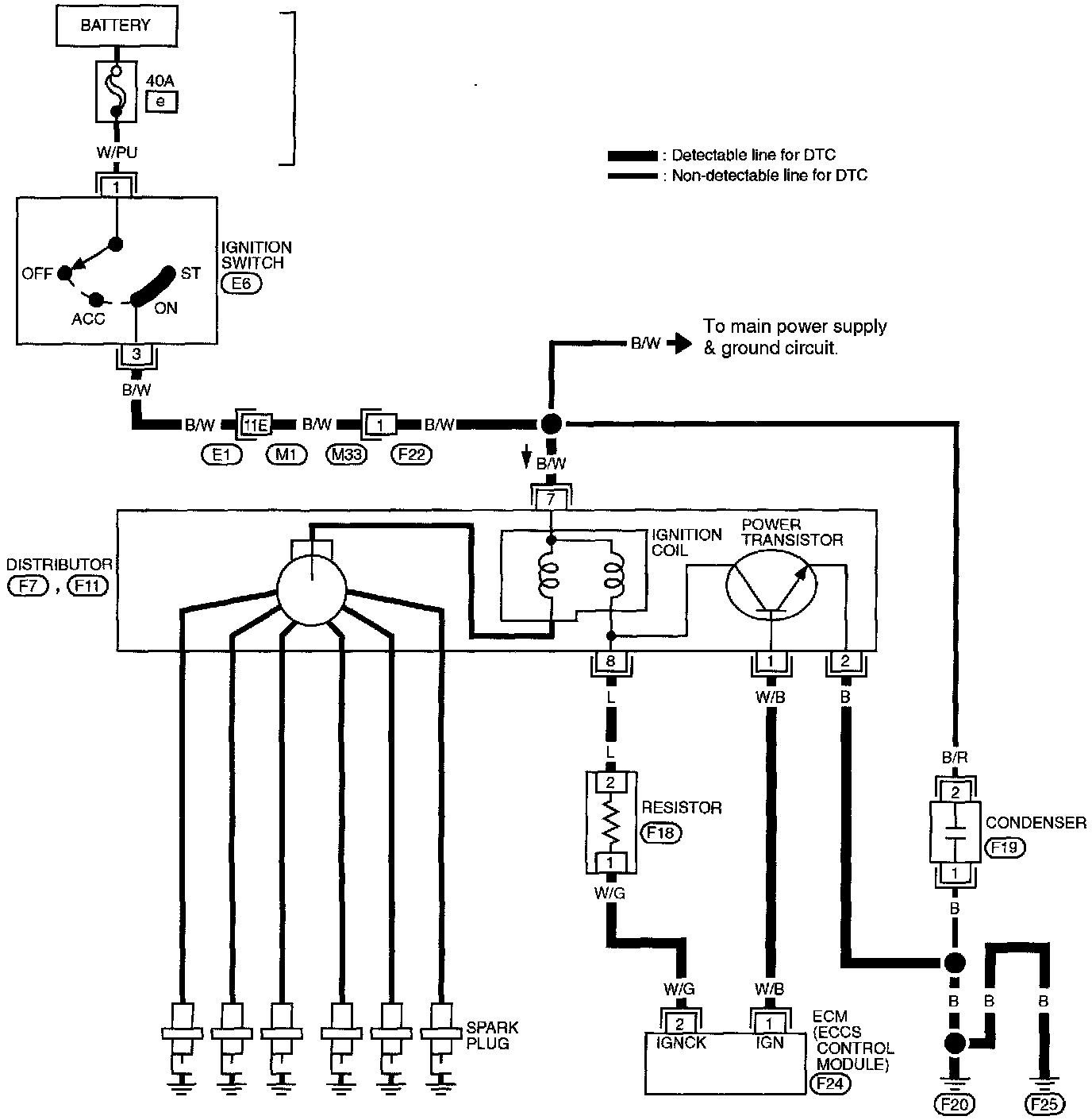
WIRING DIAGRAM
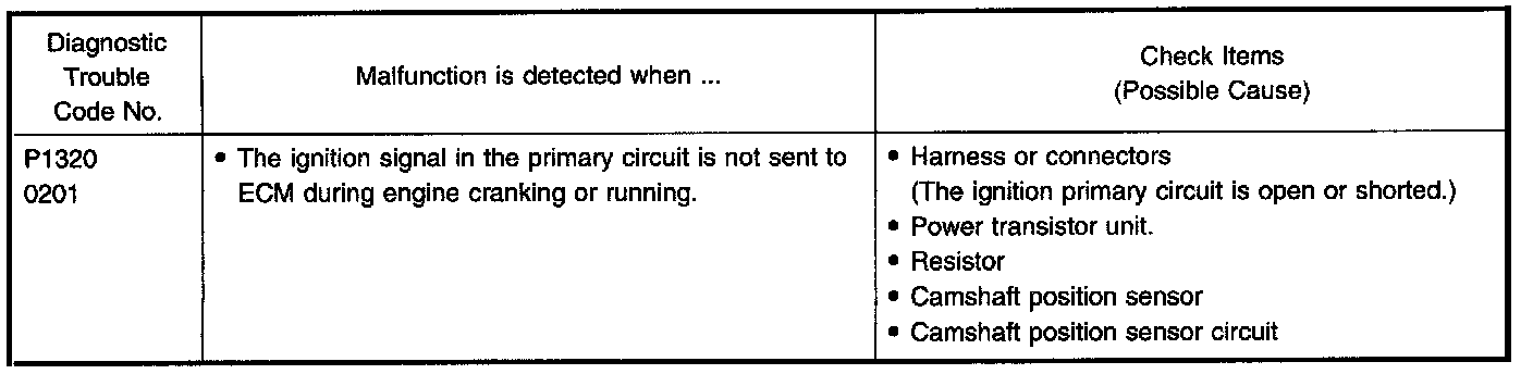
DIAGNOSTIC TROUBLE CODE CONFIRMATION PROCEDURE
NOTE: If both DTC P0340 (0101) and P1320 (0201) are displayed, perform TROUBLE DIAGNOSIS FOR DTC P0340 first.
With CONSULT
1. Turn ignition switch "ON".
2. Select "DATA MONITOR" mode with CONSULT.
3. Start engine. (If engine does not run, turn ignition switch to "START" for at least 5 seconds.)
With Generic Scan Tool (GST)
1. Turn ignition switch "ON".
2. Start engine. (If engine does not run, turn ignition switch to "START" for at least 5 seconds.)
3. Select MODE 3 with GST.
Without Tools
1. Turn ignition switch "ON".
2. Start engine. (If engine does not run, turn ignition switch to "START" for at least 5 seconds.)
3. Turn ignition switch "OFF" and wait at least 5 seconds, then turn "ON".
4. Perform "Diagnostic Test Mode II" (Self-diagnostic results) with ECM.
COMPONENT INSPECTION
Ignition Coil
1. Disconnect ignition coil harness connector.
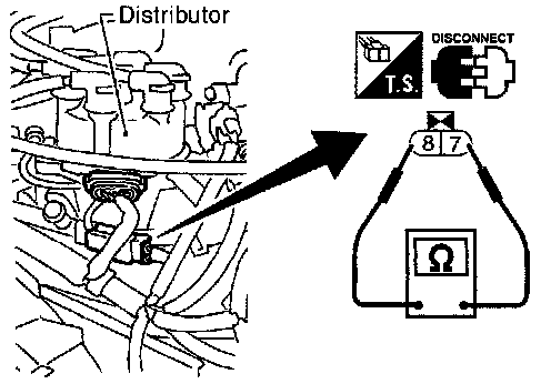
2. Check resistance as shown.
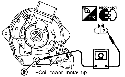
For checking secondary coil, remove distributor cap and measure resistance between coil tower metal tip (9) and terminal (7).
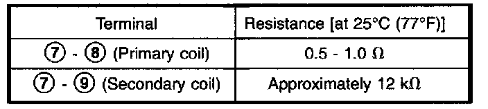
If NG, replace distributor assembly as a unit.
Power Transistor
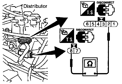
1. Disconnect camshaft position sensor & power transistor harness connector and ignition coil harness connector.
2. Check power transistor resistance between terminals (2) and (8).
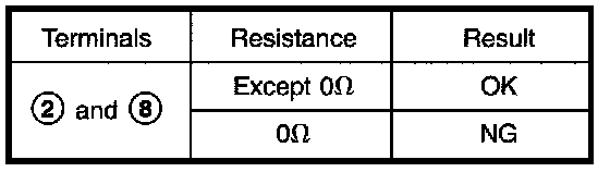
If NG, replace distributor assembly.
Resistor
1. Disconnect resistor harness connector.
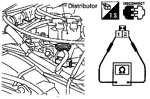
2. Check resistance between terminals (1) and (2)
Resistance: Approximately 2.2 k-ohms [at 25°C (77°F)]
If NG, replace resistor.