How to Read Wiring Diagrams
HOW TO READ WIRING DIAGRAMS
SAMPLE/WIRING DIAGRAM - EXAMPL -
- For detail, refer to following "DESCRIPTION".
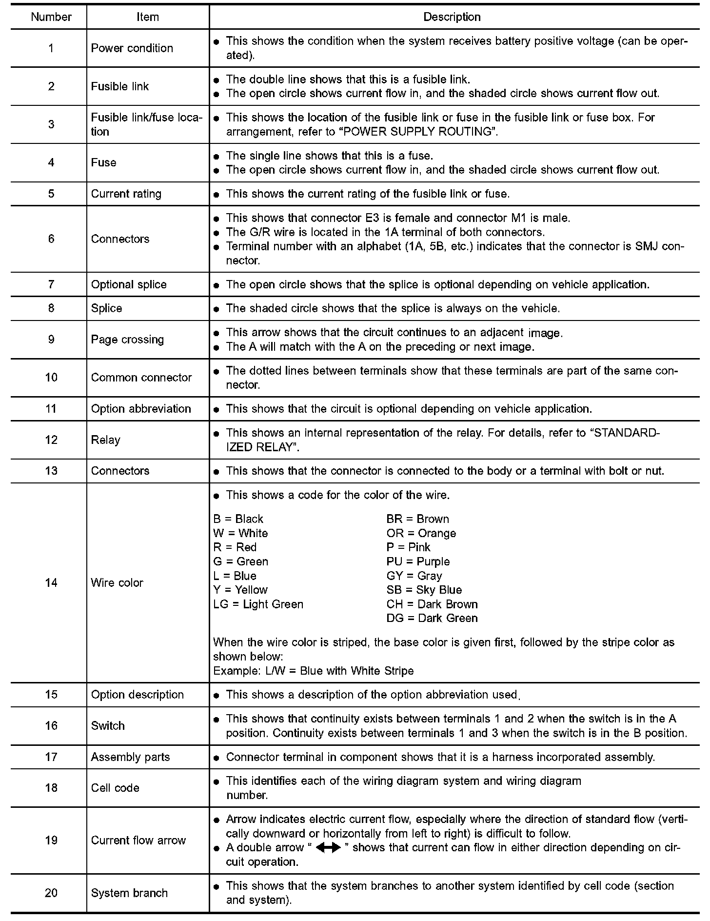
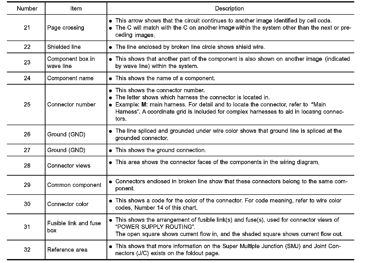
Description
CONNECTOR SYMBOLS
Most of connector symbols in wiring diagrams are shown from the I terminal side.
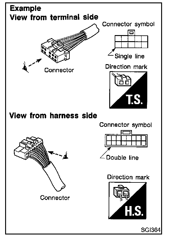
- Connector symbols shown from the terminal side are enclosed by a single line and followed by the direction mark.
- Connector symbols shown from the harness side are enclosed by a double line and followed by the direction mark.
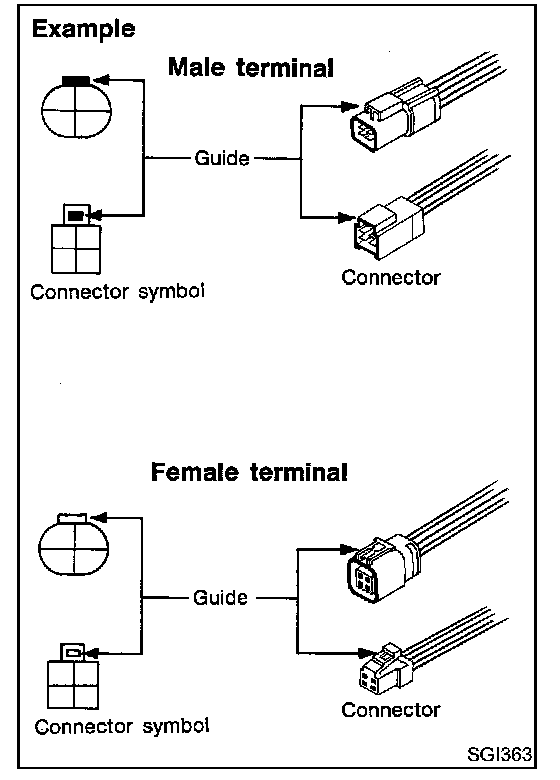
- Male and female terminals
Connector guides for male terminals are shown in black and female terminals in white in wiring diagrams.
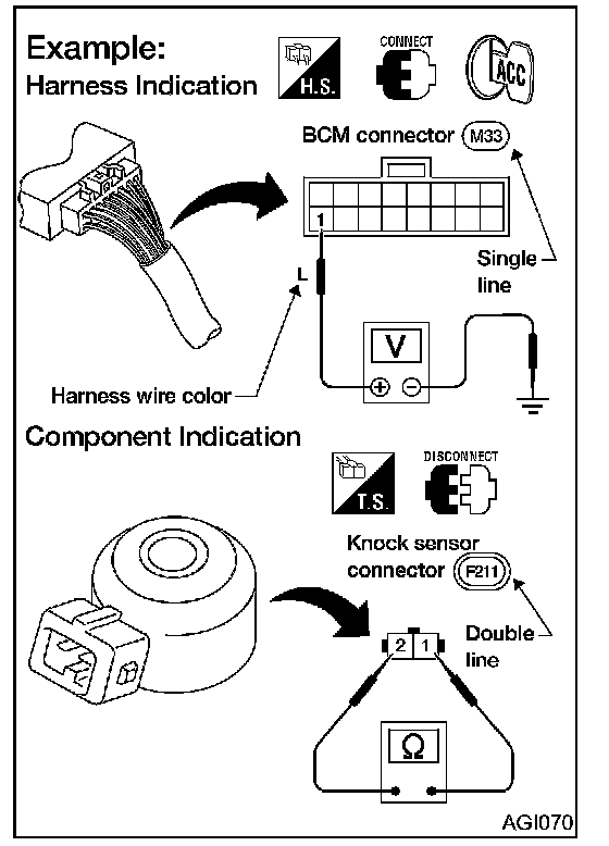
HARNESS INDICATION
- Letter designations next to test meter probe indicate harness (connector) wire color.
- Connector numbers in a single circle M33 indicate harness connectors.
COMPONENT INDICATION
- Connector numbers in a double circle F211 indicate component connectors.
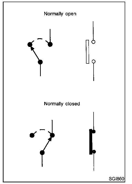
SWITCH POSITIONS
Switches are shown in wiring diagrams as if the vehicle is in the normal condition
A vehicle is in the normal condition when:
- ignition switch is OFF
- doors hood and trunk lid/back door are closed
- pedals are not depressed and
- parking brake is released.
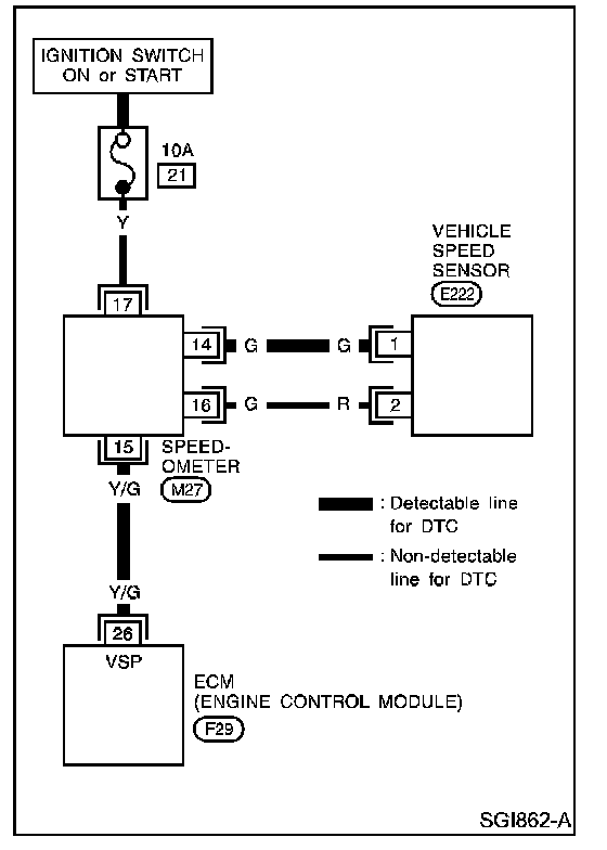
DETECTABLE LINES AND NON-DETECTABLE LINES
In some wiring diagrams two kinds of lines representing wires with different weight are used.
- A line with regular weight (wider line) represents a detectable line for "DTC (Diagnostic Trouble Code)". A detectable line for "DTC" is a circuit in which ECM (Engine Control Module) can detect its malfunctions with the on board diagnostic system.
- A line with less weight (thinner line) represents a "non-detectable line" for "DTC". A non-detectable line for "DTC" is a circuit in which ECM cannot detect its malfunctions with the on board diagnostic system.
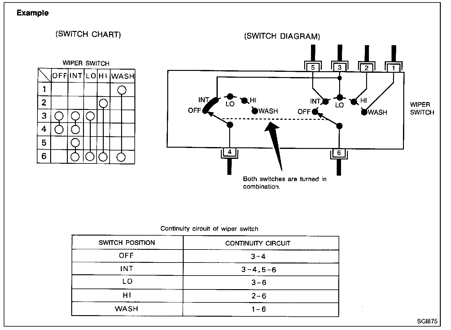
MULTIPLE SWITCH
The continuity of multiple switch is described in two ways as shown.
- The switch chart is used in schematic diagrams.
- The switch diagram is used in wiring diagrams.