On Board Diagnostic (OBD) System Precautions
Precautions for On Board Diagnostic (OBD) System of Engine and A/TThe ECM has an on board diagnostic system. It will light up the malfunction indicator lamp (MIL) to warn the driver of a malfunction causing emission deterioration.
CAUTION:
- Be sure to turn the ignition switch OFF and disconnect the negative battery terminal before any repair or inspection work. The open/short circuit of related switches, sensors, solenoid valves, etc. will cause the MIL to light up.
- Be sure to connect and lock the connectors securely after work. A loose (unlocked) connector will cause the MIL to light up due to the open circuit. (Be sure the connector is free from water, grease, dirt, bent terminals, etc.)
- Certain systems and components, especially those related to OBD, may use a new style slide-locking type harness connector.
For description and how to disconnect, refer to "HARNESS CONNECTOR". Diagram Information and Instructions
- Be sure to route and secure the harnesses properly after work. The interference of the harness with a bracket, etc. may cause the MIL to light up due to the short circuit.
- Be sure to connect rubber tubes properly after work. A misconnected or disconnected rubber tube may cause the MIL to light up due to the malfunction of the EGR system or fuel injection system,etc.
- Be sure to erase the unnecessary malfunction information (repairs completed) from the ECM before returning the vehicle to the customer.
Precautions
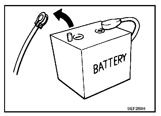
- Before connecting or disconnecting the ECM harness connector, turn ignition switch OFF and disconnect negative battery terminal. Failure to do so may damage the ECM because battery voltage is applied to ECM even if ignition switch is turned OFF.
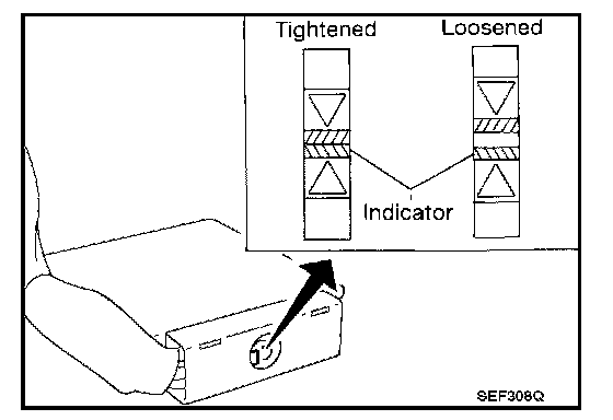
- When connecting ECM harness connector, tighten securing bolt until the gap between orange indicators disappears.
Torque: 3 - 5 Nm (0.3 - 0.5 kg-m, 26 - 43 in-lb)
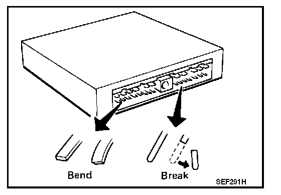
- When connecting or disconnecting pin connectors into or from ECM, take care not to damage pin terminals (bend or break).
Make sure that there are not any bends or breaks on ECM pin terminals when connecting pin connectors.
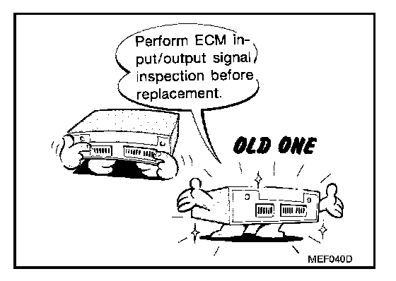
- Before replacing ECM, perform Terminals and Reference Value inspection and make sure ECM functions properly.
- After performing each TROUBLE DIAGNOSIS, perform "Overall Function Check" or "DTC Confirmation Procedure".
The DTC should not be displayed in the "DTC Confirmation Procedure" if the repair is completed. The "Overall Function Check" should be a good result if the repair is completed.
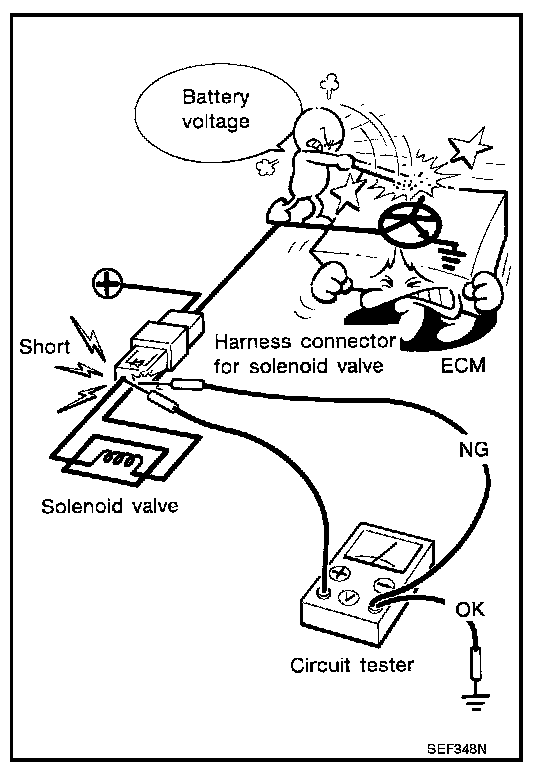
- When measuring ECM signals with a circuit tester, never allow the two tester probes to contact.
Accidental contact of probes will cause a short circuit and damage the ECM power transistor.
- Do not use ECM ground terminals when measuring input/ output voltage. Doing so may result in damage to the ECM's transistor. Use a ground other than the ECM terminals, such as the ground.