Precautions For CVT Assembly Replacement
Precautions for CVT Assembly ReplacementCAUTION:
^ Check if new data (Unit ID) are entered correctly after replacing CVT assembly and erasing data in TCM. (Connect CONSULT-II, and then turn ignition switch OFF.)
^ When replacing CVT assembly or TCM, refer to the pattern table and erase the EEPROM in the TCM if necessary.
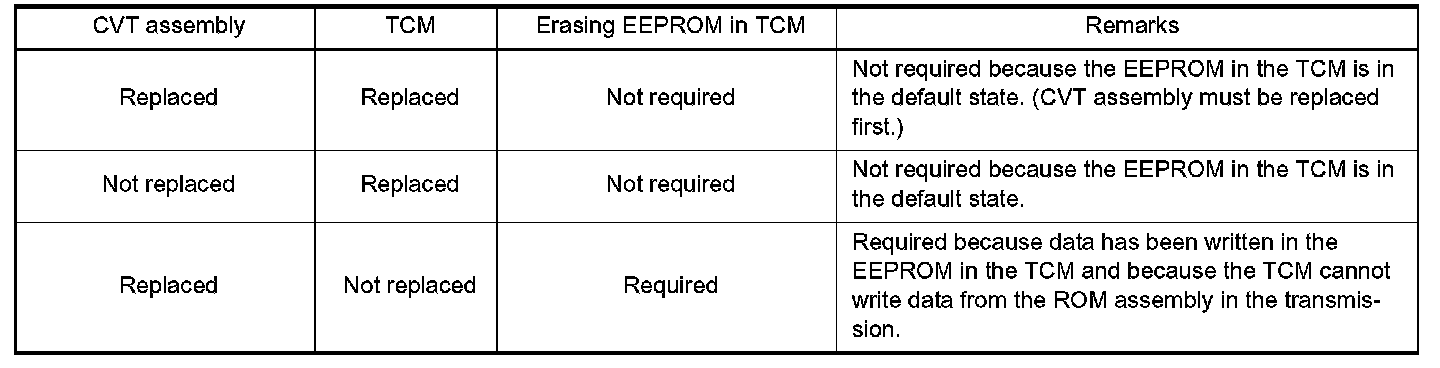
EEPROM ERASING PATTERNS
METHOD FOR ERASING THE EEPROM IN THE TCM
1. Connect CONSULT-II to data link connector.
2. Turn ignition switch ON. Confirm that CONSULT-II is turned "ON".
3. Move selector lever to "R" position.
4. Touch "START (NISSAN BASED VHCL)" on CONSULT-II.
5. Select "SELF-DIAG RESULTS" mode for "TRANSMISSION" with CONSULT-II.
6. Brake switch "ON".
7. Press the accelerator pedal (0.5/8 - 4/8 throttle) not to exceed the half, and hold it in the half or less open position. (This will set the closed throttle position signal to "OFF" and the wide open throttle position signal to "OFF".)
8. Touch "ERASE" on CONSULT-II, and then touch "YES".
9. Wait 3 seconds and then release the accelerator pedal.
10. Turn ignition switch OFF.
METHOD FOR WRITING DATA FROM THE ROM ASSEMBLY IN THE TRANSMISSION
In the following procedure, the TCM reads data from the ROM assembly and writes it to the EEPROM in the TCM.
1. With the EEPROM in the TCM erased.
2. Move selector lever to "P" position.
3. Turn ignition switch ON.
CHECK METHOD
^ Normal: About 2 seconds after the ignition switch ON. the CVT indicator lamp lights up for 2 seconds.
^ Non-standard: Even after the ignition switch ON, the CVT indicator lamp does not light up after 2 seconds or illuminates immediately.
CAUTION: Perform in the P or N position.
Cope for non-standard
^ Replace the CVT assembly.
^ Replace the TCM.
Removal and Installation Procedure for CVT Unit Connector
REMOVAL
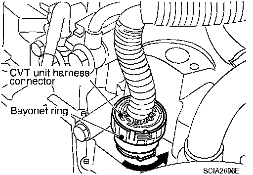
^ Rotate bayonet ring counterclockwise, pull out CVT unit harness connector upward and remove it.
INSTALLATION
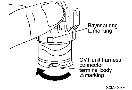
1. Align marking on CVT unit harness connector terminal body with marking on bayonet ring, insert CVT unit harness connector, and then rotate bayonet ring clockwise.
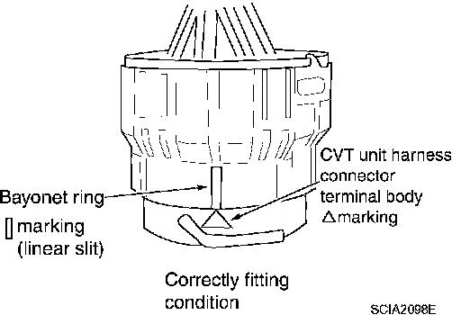
2. Rotate bayonet ring clockwise until ^ marking on CVT unit harness connector terminal body is aligned with the slit on bayonet ring as shown in the figure (correctly fitting condition), install CVT unit harness connector to CVT unit harness connector terminal body.
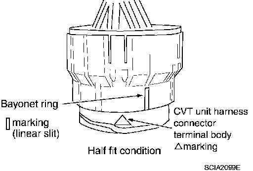
CAUTION:
^ Securely align marking on CVT unit harness connector terminal body with bayonet ring slit. Then, be careful not to make a half fit condition as shown in the figure.
^ Do not mistake the slit of bayonet ring for other dent portion.