How to Read Wiring Diagrams
HOW TO READ WIRING DIAGRAMSGI-EXAMPL-02:
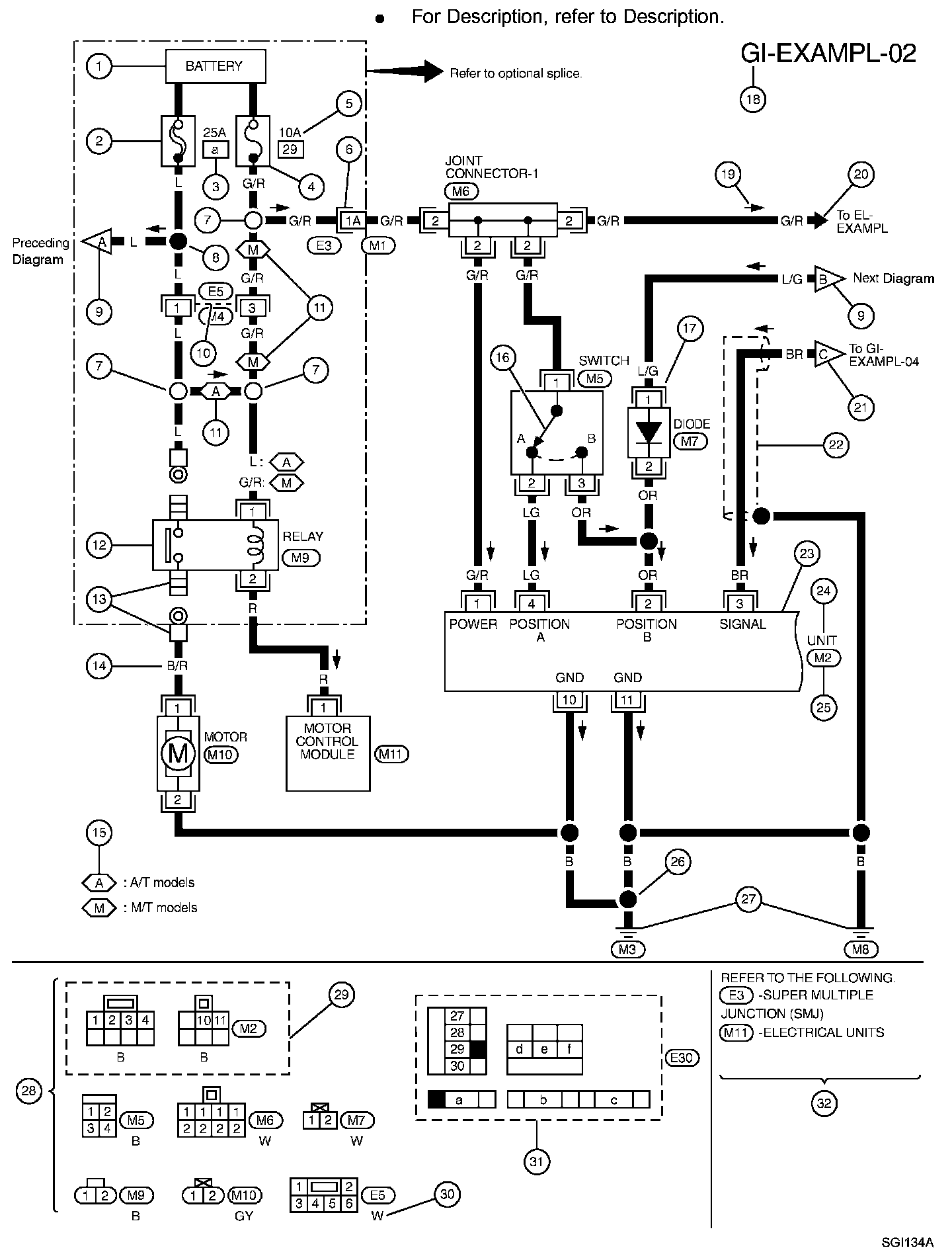
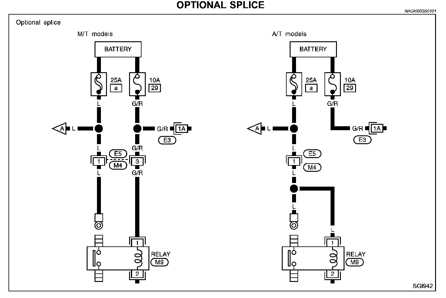
SAMPLE/WIRING DIAGRAM - EXAMPLE -
Part 1:
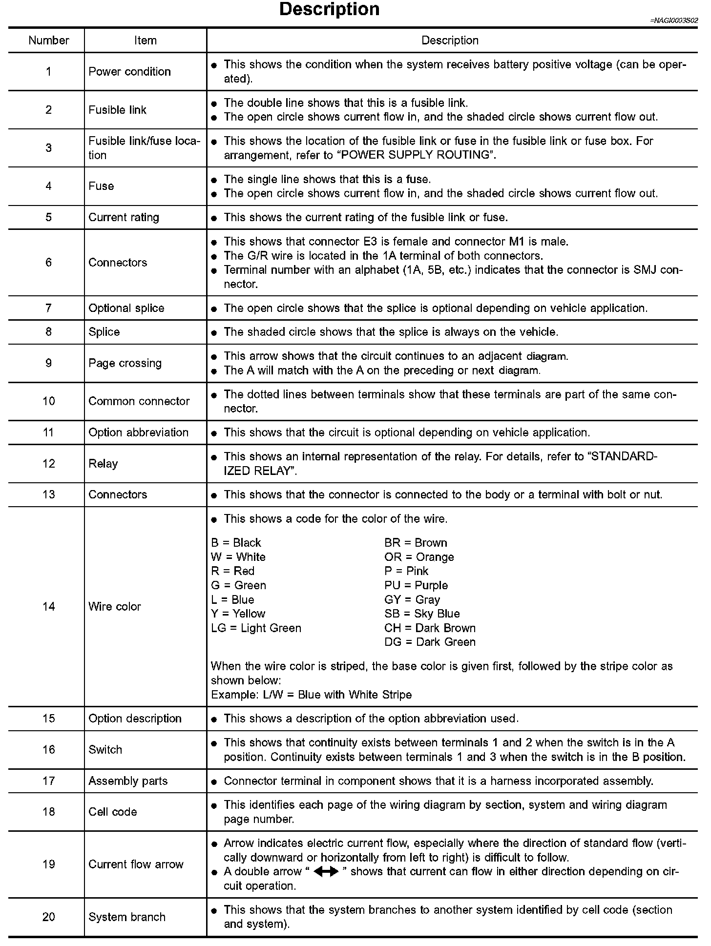
Part 2:
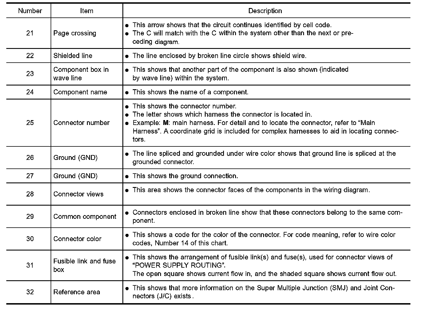
Description
CONNECTOR SYMBOLS
Most of connector symbols in wiring diagrams are shown from the I terminal side.
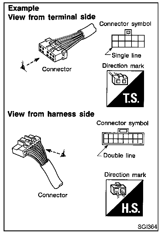
- Connector symbols shown from the terminal side are enclosed by a single line and followed by the direction mark.
- Connector symbols shown from the harness side are enclosed by a double line and followed by the direction mark.
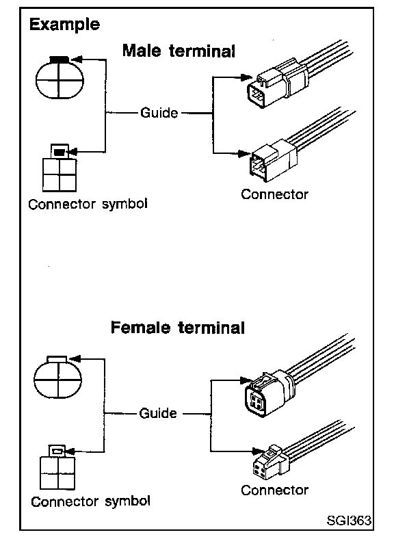
- Male and female terminals
Connector guides for male terminals are shown in black and female terminals in white in wiring diagrams.
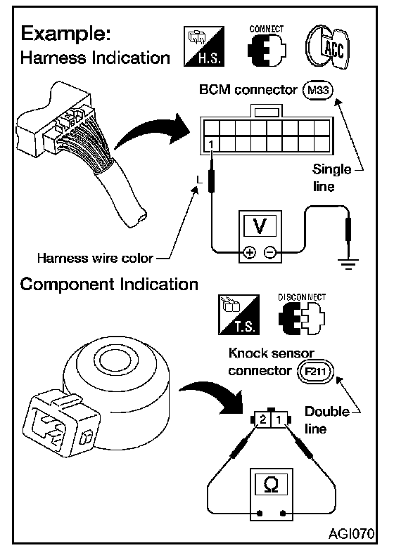
HARNESS INDICATION
- Letter designations next to test meter probe indicate harness (connector) wire color.
- Connector numbers in a single circle M33 indicate harness connectors.
COMPONENT INDICATION
- Connector numbers in a double circle F211 indicate component connectors.
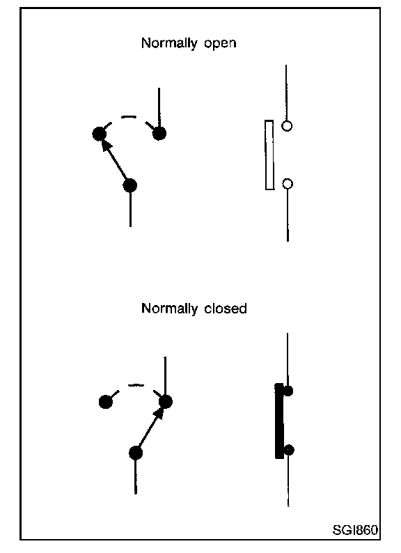
SWITCH POSITIONS
Switches are shown in wiring diagrams as if the vehicle is in the normal condition
A vehicle is in the normal condition when:
- ignition switch is OFF
- doors hood and trunk lid/back door are closed
- pedals are not depressed and
- parking brake is released.
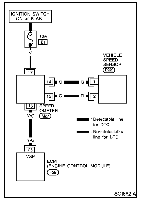
DETECTABLE LINES AND NON-DETECTABLE LINES
In some wiring diagrams two kinds of lines representing wires with different weight are used.
- A line with regular weight (wider line) represents a detectable line for "DTC (Diagnostic Trouble Code)". A detectable line for "DTC" is a circuit in which ECM (Engine Control Module) can detect its malfunctions with the on board diagnostic system.
- A line with less weight (thinner line) represents a "non-detectable line" for "DTC". A non-detectable line for "DTC" is a circuit in which ECM cannot detect its malfunctions with the on board diagnostic system.
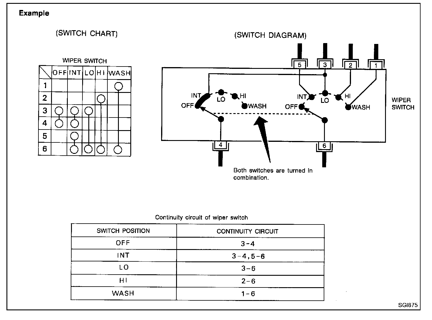
MULTIPLE SWITCH
The continuity of multiple switch is described in two ways as shown.
- The switch chart is used in schematic diagrams.
- The switch diagram is used in wiring diagrams.
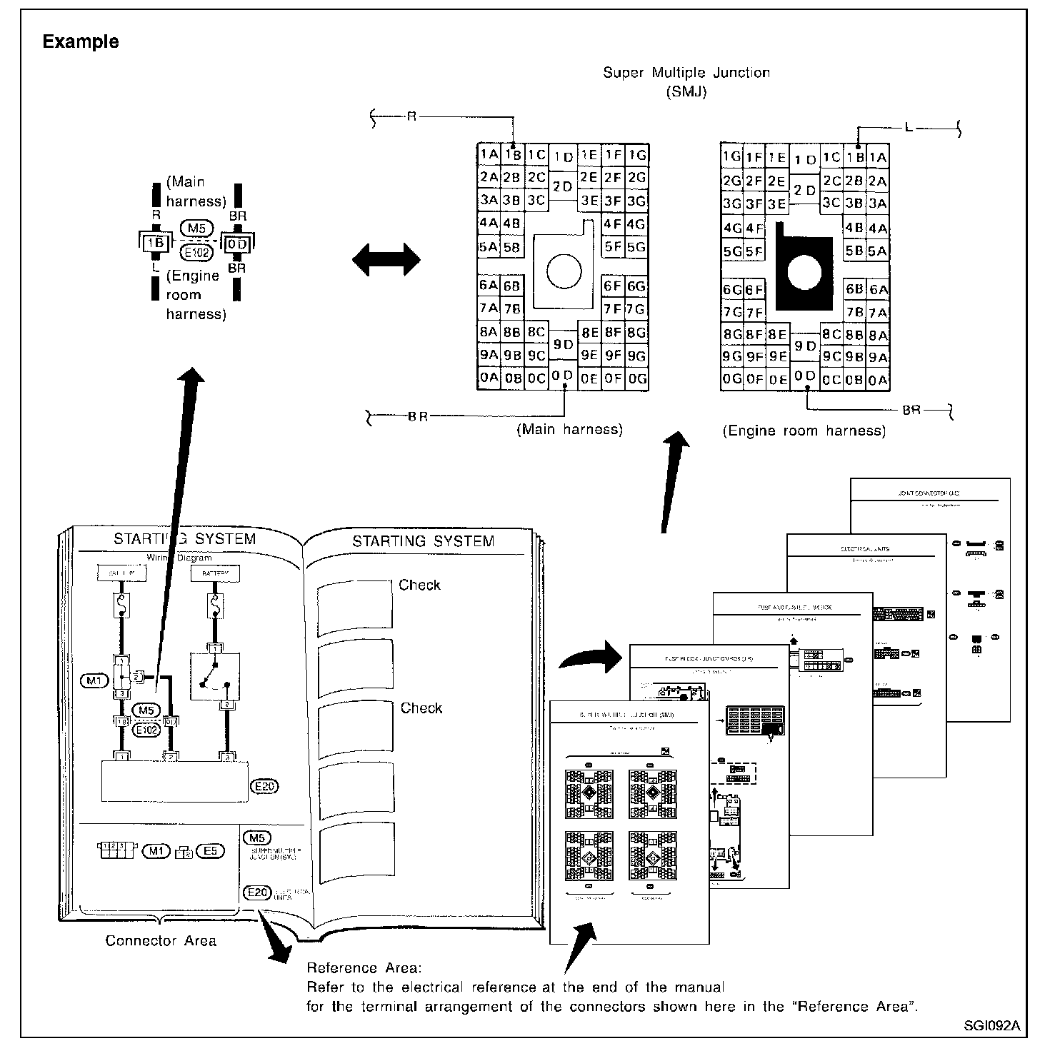
Reference Area
The Reference Area of the wiring diagram contains references to additional electrical reference pages at the end of the manual. If connector numbers and titles are shown in the Reference Area of the wiring diagram, these connector symbols are not shown in the Connector Area.
Super Multiple Junction (SMJ)
In a wiring diagram, the SMJ connectors include a letter of the alphabet in the terminal number.
SMJ connector numbers are shown in the Reference Area of the wiring diagram. SMJ terminal arrangement can be found on the electrical reference pages at the end of the manual. For terminal arrangement of these connectors, refer to the "SUPER MULTIPLE JUNCTION (SMJ)".
Fuse block-Junction Box (J/B)
Fuse block-Junction Box (J/B) connector number is shown in the Reference Area of the wiring diagram.
For connector terminal and fuse arrangement, refer to the "FUSE BLOCK-Junction Box (J/B)".
Fuse and fusible link box
For fuse arrangement in the fuse and fusible link box, refer to the "FUSE AND FUSIBLE LINK BOX".
Electrical units
Electrical unit connector symbols are shown in the Connector Area of the wiring diagram.
However, when there is not enough space to show the connector terminal arrangement in the Connector Area of the wiring diagram, the electrical unit connector number is shown in the Reference Area of the wiring diagram.
For electrical unit connector terminal arrangement, refer to the "ELECTRICAL UNITS" electrical reference. Most of the electrical unit connectors are shown from the harness side of the connector.
Joint Connector
Joint Connector symbols are shown in the connector area of the wiring diagram. For connector internal wiring layout and joint connector terminal arrangement, refer to the "JOINT CONNECTOR (J/C)".