Connecting Rod Bearing
CONNECTING ROD BUSHING OIL CLEARANCE (SMALL END)Inner Diameter of Connecting Rod (Small End)
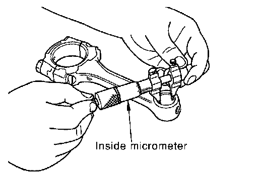
^ Measure inner diameter of bushing.
Outer Diameter of Piston Pin
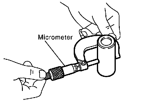
^ Measure outer diameter of piston pin.
Connecting Rod Bushing Oil Clearance (Small End)
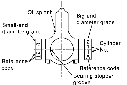
(Connecting rod small end oil clearance) = (Inner diameter of connecting rod small end) - (Outer diameter of piston pin)
Standard: 0.005 - 0.017 mm (0.0002 - 0.0007 inch)
^ If the measured value exceeds the standard, replace the connecting rod assembly and/or piston and piston pin assembly.
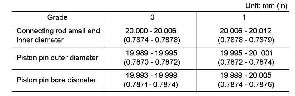
^ If replacing the piston and piston pin assembly, refer to the "Piston Selection Table" to select the piston corresponding to the applicable bore grade of the cylinder block to be used.
Factory Installed Parts Grading:
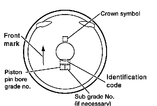
^ Service parts apply only to grade 0.
OIL CLEARANCE OF CONNECTING ROD BEARING
Method of Measurement
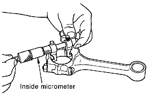
^ Install the connecting rod bearings to the connecting rod and the cap, and tighten the connecting rod bolts to the specified torque. Using a inside micrometer measure the inner diameter of connecting rod bearing.
(Oil clearance) = (Inner diameter of connecting rod bearing) - (Outer diameter of crankshaft pin)
Standard: 0.028 - 0.045 mm (0.0011 - 0.0018 inch)
Limit: 0.10 mm (0.0039 inch)
^ If clearance cannot be adjusted within the standard, grind crankshaft pin and use undersized bearing.
Method of Using Plastigage
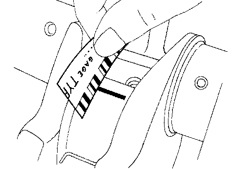
^ Remove oil and dust on the crankshaft pin and the surfaces of each bearing completely.
^ Cut the Plastigage slightly shorter than the bearing width, and place it in crankshaft axial direction, avoiding oil holes.
^ Install the connecting rod bearings to the connecting rod cap, and tighten the connecting rod bolts to the specified torque.
CAUTION: Never rotate the crankshaft.
^ Remove the connecting rod cap and bearings, and using the scale on the Plastigage bag, measure the Plastigage width.
NOTE: The procedure when the measured value exceeds the limit is same as that described in the method by calculation.
Rod Bearing Cap
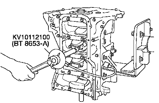
Tighten the connecting rod bolt as follows: Apply engine oil to the threads and seats of the connecting rod bolts.
CAUTION: Check tightening angle. Do not make judgment by visual inspection.
Tool number: KV10112100 (BT-8653-A)
Stage 1 18.6 - 20.6 Nm (1.9 - 2.1 kg-m, 14 - 15 ft. lbs.)
Stage 2 Rotate bolts 85° - 95° (target 90°)
Check the connecting rod side clearance.
After tightening the bolts, make sure that the crankshaft rotates smoothly.
OUTER DIAMETER OF CONNECTING ROD BOLT
^ Measure outer diameter (d) at position as shown.
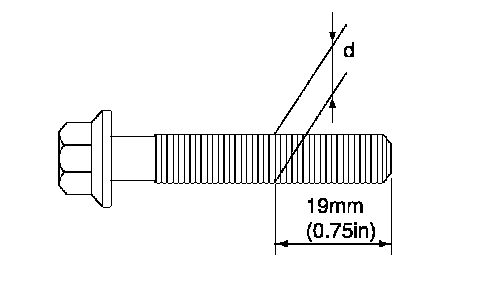
^ When d exceeds the limit (when it becomes thinner), replace the bolt with a new one.
Limit 7.75 mm (0.3051 inch) or less
CONNECTING ROD BEARING:

CONNECTING ROD BEARING
Undersize:

Undersize
Bearing Clearance:

Bearing Clearance