Service Limits & General Specifications
CRANKSHAFT END PLAY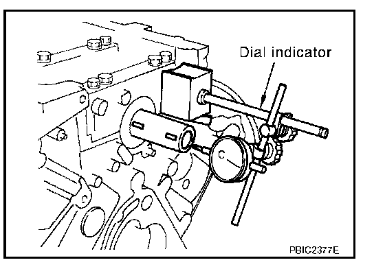
^ Measure the clearance between thrust bearings and crankshaft arm when crankshaft is moved fully forward or backward with a dial indicator.
Standard: 0.10 - 0.26 mm (0.0039 - 0.0102 in)
Limit: 0.30 mm (0.0118 in)
^ If the measured value exceeds the limit, replace thrust bearings, and measure again. If it still exceeds the limit, replace crankshaft also.
CONNECTING ROD SIDE CLEARANCE
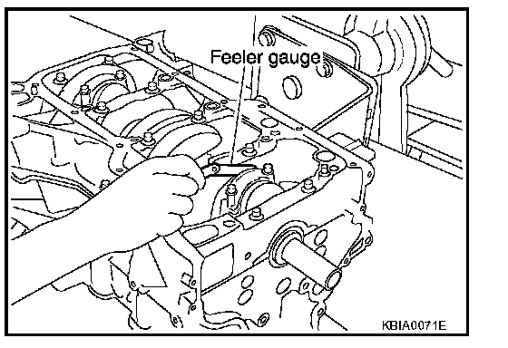
^ Measure the side clearance between connecting rod and crankshaft arm with a feeler gauge.
Standard: 0.20 - 0.25 mm (0.0079 - 0.098 in)
Limit: 0.50 mm (0.0197 in)
^ If the measured value exceeds the limit, replace connecting rod, and measure again. If it still exceeds the limit, replace crankshaft also.
PISTON TO PISTON PIN OIL CLEARANCE
Piston Pin Hole Diameter
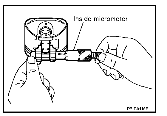
Measure the inner diameter of piston pin hole with an inside micrometer.
Standard: 19.993 - 20.005 mm (0.7871 - 0.7876 in)
Piston Pin Outer Diameter
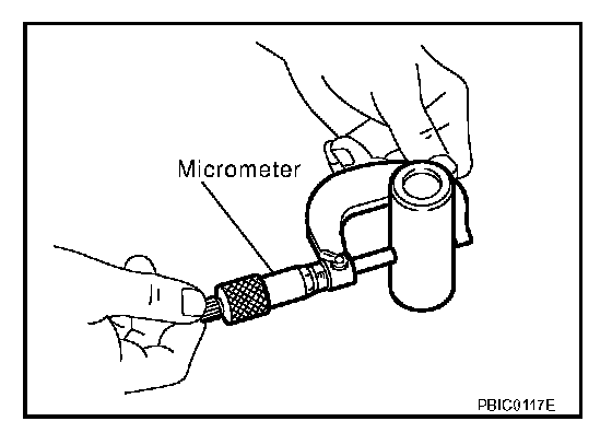
Measure the outer diameter of piston pin with a micrometer.
Standard: 19.989 - 20.001 mm (0.7870 - 0.7874 in)
Piston to Piston Pin Oil Clearance
(Piston to piston pin oil clearance) = (Piston pin hole diameter) - (Piston pin outer diameter)
Standard: 0.002 - 0.006 mm (0.0001 - 0.0002 in)
^ If oil clearance is out of the standard, replace piston and piston pin assembly.
^ When replacing piston and piston pin assembly, refer to "Piston to Cylinder Bore Clearance".
NOTE:
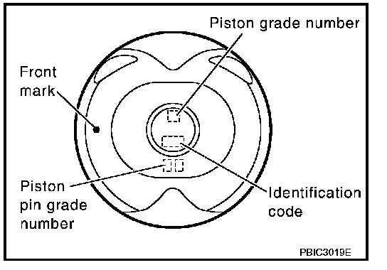
^ Piston is available together with piston pin as assembly.
^ Piston pin (piston pin hole) grade is provided only for the parts installed at the plant. For service parts, no grades can be selected. (Only grade "0" is available.)
PISTON RING SIDE CLEARANCE
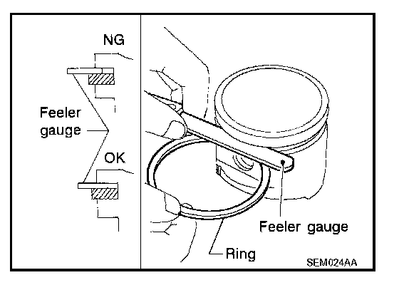
^ Measure the side clearance of piston ring and piston ring groove with a feeler gauge.
Standard:
Top ring: 0.045 - 0.080 mm (0.0018 - 0.0031 in)
2nd ring: 0.030 - 0.070 mm (0.0012 - 0.0028 in)
Oil ring: 0.065 - 0.135 mm (0.0026 - 0.0053 in)
Limit:
Top ring: 0.11 mm (0.0043 in)
2nd ring: 0.10 mm (0.0039 in)
^ If the measured value exceeds the limit, replace piston ring, and measure again. If it still exceeds the limit, replace piston also.
PISTON RING END GAP
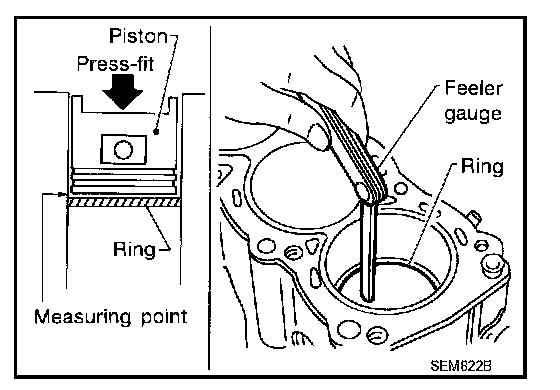
^ Make sure that cylinder bore inner diameter is within the specification. Refer to "Cylinder Bore Inner Diameter".
^ Lubricate with new engine oil to piston and piston ring, and then insert piston ring until middle of cylinder with piston, and measure piston ring end gap with a feeler gauge.
Standard:
Top ring: 0.21 - 0.31 mm (0.0083 - 0.0122 in)
2nd ring: 0.32 - 0.47 mm (0.0126 - 0.0185 in)
Oil ring (rail ring): 0.20 - 0.60 mm (0.0079 - 0.0236 in)
Limit:
Top ring: 0.54 mm (0.0213 in)
2nd ring: 0.65 mm (0.0256 in)
Oil ring (rail ring): 0.95 mm (0.0374 in)
^ If the measured value exceeds the limit, replace piston ring, and measure again. If it still exceeds the limit, re-bore cylinder inner wall and use oversized piston and piston rings.
CONNECTING ROD BEND AND TORSION
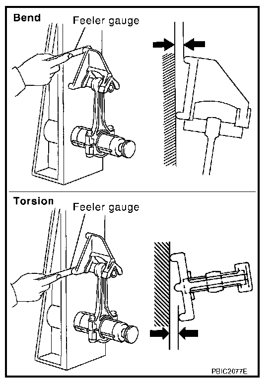
^ Check with a connecting rod aligner.
Bend:
Limit: 0.15 mm (0.0059 in) per 100 mm (3.94 in) length
Torsion:
Limit: 0.30 mm (0.0118 in) per 100 mm (3.94 in) length
^ If it exceeds the limit, replace connecting rod assembly.
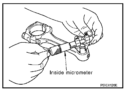
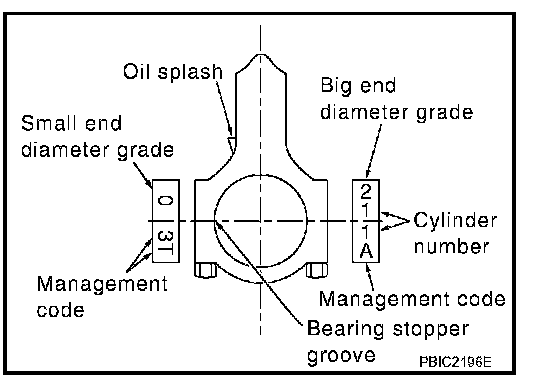
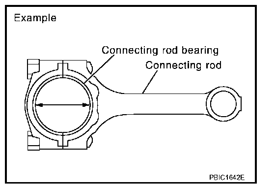
CONNECTING ROD BIG END DIAMETER
^ Install connecting rod cap without connecting rod bearing installed, and tightening connecting rod bolts to the specified torque. Refer to EM-80, "ASSEMBLY" for the tightening procedure. Disassembly and Assembly
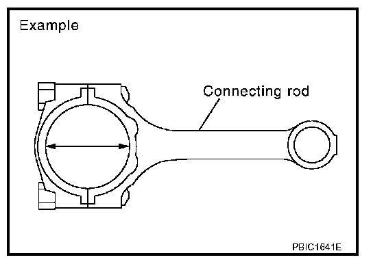
^ Measure the inner diameter of connecting rod big end with an inside micrometer.
Standard: 48.000 - 48.013 mm (1.8898 - 1.8903 in)
^ If out of the standard, replace connecting rod assembly.
CONNECTING ROD BUSHING OIL CLEARANCE
Connecting Rod Bushing Inner Diameter
Measure the inner diameter of connecting rod bushing with an inside micrometer.
Standard: 20.000 - 20.012 mm (0.7874 - 0.7879 in)
Piston Pin Outer Diameter
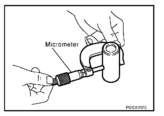
Measure the outer diameter of piston pin with a micrometer.
Standard: 19.989 - 20.001 mm (0.7870 - 0.7874 in)
Connecting Rod Bushing Oil Clearance
(Connecting rod bushing oil clearance) = (Connecting rod bushing inner diameter) - (Piston pin outer diameter)
Standard: 0.005 - 0.017 mm (0.0002 - 0.0007 in)
^ If the measured value is out of the standard, replace connecting rod assembly and/or piston and piston pin assembly.
^ If replacing piston and piston pin assembly, refer to "PISTON TO CYLINDER BORE CLEARANCE".
^ If replacing connecting rod assembly, refer to "CONNECTING ROD BEARING OIL CLEARANCE" to select connecting rod bearing.
Factory installed parts grading:
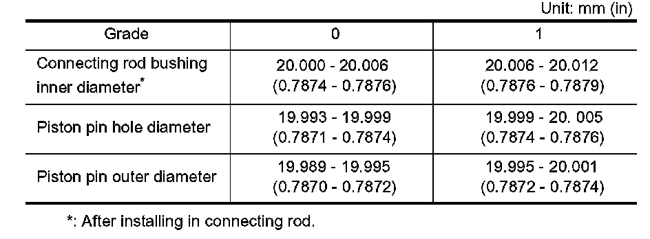
^ Service parts apply only to grade "0".
CYLINDER BLOCK DISTORTION
^ Remove gasket on the cylinder block surface, and also remove engine oil, scale, carbon, or other contamination; using suitable tool.
CAUTION: Be careful not to allow gasket flakes to enter engine oil or engine coolant passages.
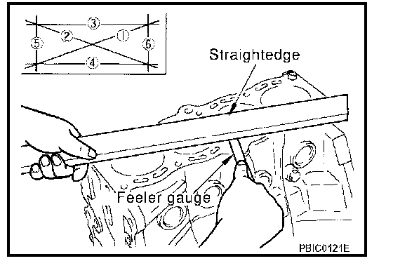
^ Measure the distortion on the cylinder block upper face at some different points in six directions with a straight edge and a feeler gauge.
Limit: 0.1 mm (0.004 in)
^ If it exceeds the limit, replace cylinder block and lower cylinder block assembly.
NOTE: Cylinder block cannot be replaced as a single, because it is machined together with lower cylinder block.
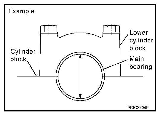
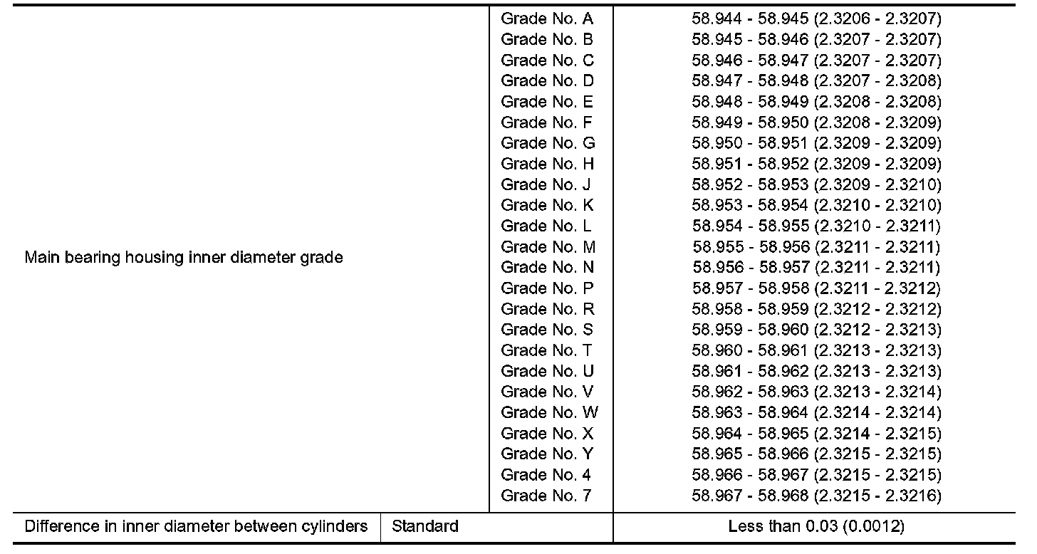
MAIN BEARING HOUSING INNER DIAMETER
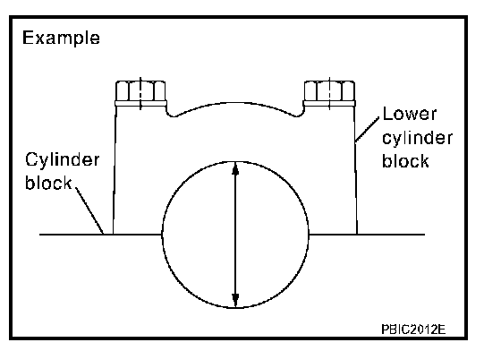
^ Install lower cylinder block without main bearings installed, and tighten lower cylinder block bolts to the specified torque. Refer to EM-80, "ASSEMBLY" for the tightening procedure. Disassembly and Assembly
^ Measure the inner diameter of main bearing housing with a bore gauge.
Standard: 58.944 - 58.968 mm (2.3206 - 2.3216 in)
^ If out of the standard, replace cylinder block and lower cylinder block assembly.
NOTE: Cylinder block cannot be replaced as a single, because it is machined together with lower cylinder block.
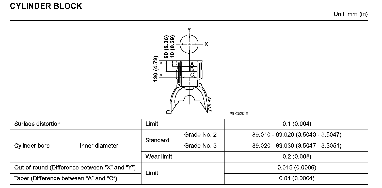
PISTON TO CYLINDER BORE CLEARANCE
Cylinder Bore Inner Diameter
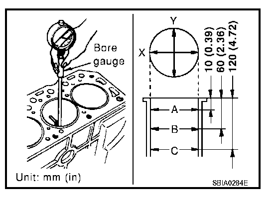
^ Using a bore gauge, measure the cylinder bore for wear, out-of-round and taper at six different points on each cylinder. ("X" and "Y" directions at "A", "B" and "C") ("Y" is in longitudinal direction of the engine)
NOTE: When determining cylinder bore grade, measure cylinder bore at "B" position.
Standard inner diameter: 89.010 - 89.030 mm (3.5043 - 3.5051 in)
Wear limit: 0.2 mm (0.008 in)
Out-of-round (Difference between "X" and "Y"): 0.015 mm (0.0006 in)
Taper limit (Difference between "A" and "C"): 0.01 mm (0.0004 in)
^ If the measured value exceeds the limit, or if there are scratches and/or seizure on the cylinder inner wall, hone or re-bore the cylinder inner wall.
^ Oversize piston is provided. When using oversize piston, re-bore the cylinder so that the clearance of the piston to cylinder bore satisfies the standard.
CAUTION: When using an oversize piston, use oversize pistons for all cylinders with oversize piston rings.
Oversize (OS): 0.2 mm (0.008 in)
Piston Skirt Diameter
Measure the outer diameter of piston skirt with a micrometer.
Measure point: Distance from the top 42.98 mm (1.692 in)
Standard: 88.990 - 89.010 mm (3.5035 - 3.5043 in)
Piston to Cylinder Bore Clearance
Calculate by piston skirt diameter and cylinder bore inner diameter (direction "X", position "B").
(Clearance) = (Cylinder bore inner diameter) - (Piston skirt diameter)
Standard: 0.010 - 0.030 mm (0.0004 - 0.0012 in)
Limit: 0.08 mm (0.0031 in)
^ If it exceeds the limit, replace piston and piston pin assembly. Refer to EM-85, "HOW TO SELECT PISTON". How to Select Piston and Bearing
Re-boring Cylinder Bore
1. Cylinder bore size is determined by adding piston to cylinder bore clearance to piston skirt diameter.
Re-bored size calculation: D = A + B - C where,
D: Bored diameter
A: Piston diameter as measured
B: Piston - to - cylinder bore clearance (standard value)
C: Honing allowance 0.02 mm (0.0008 in)
2. Install lower cylinder block, and tighten bolts to the specified torque. Otherwise, cylinder bores may be distorted in final assembly. Refer to EM-80, "ASSEMBLY" for the tightening procedure. Disassembly and Assembly
3. Cut cylinder bores.
NOTE:
^ When any cylinder needs boring, all other cylinders must also be bored.
^ Do not cut too much out of cylinder bore at a time. Cut only 0.05 mm (0.0020 in) or so in diameter at a time.
4. Hone cylinders to obtain the specified piston to cylinder bore clearance.
5. Measure the finished cylinder bore for out-of-round and taper.
NOTE: Measurement should be done after cylinder bore cools down.
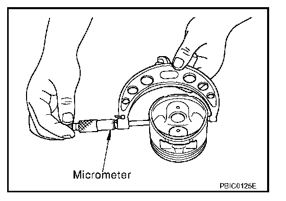
CONNECTING ROD BEARING OIL CLEARANCE
Method by Calculation
^ Install connecting rod bearings to connecting rod and cap, and tighten connecting rod bolts to the specified torque. Refer to EM-80, "ASSEMBLY" for tightening procedure. Disassembly and Assembly
^ Measure the inner diameter of connecting rod bearing with an inside micrometer.
(Bearing oil clearance) = (Connecting rod bearing inner diameter) - (Crankshaft pin journal diameter)
Standard: 0.035 - 0.045 mm (0.0014 - 0.0018 in)
^ If the clearance exceeds the limit, select proper connecting rod bearing according to connecting rod big end diameter and crankshaft pin journal diameter to obtain the specified bearing oil clearance.
Method of Using Plastigage
^ Remove engine oil and dust on crankshaft pin and the surfaces of each bearing completely.
^ Cut a plastigage slightly shorter than the bearing width, and place it in crankshaft axial direction, avoiding oil holes.
^ Install connecting rod bearings to connecting rod and cap, and tighten connecting rod bolts to the specified torque. Refer to EM-80, "ASSEMBLY" for the tightening procedure. Disassembly and Assembly
CAUTION: Do not rotate crankshaft.
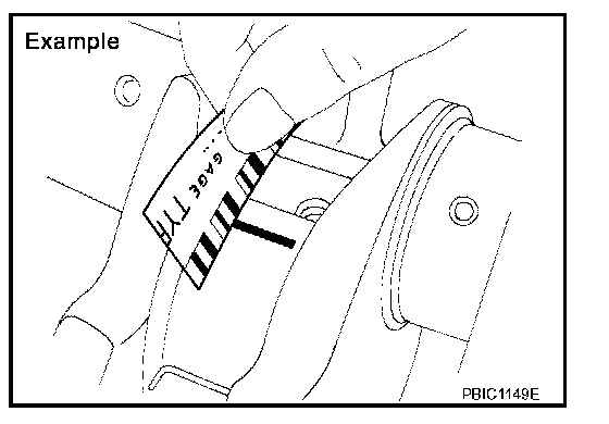
^ Remove connecting rod cap and bearing, and using the scale on the plastigage bag, measure the plastigage width.
NOTE: The procedure when the measured value exceeds the limit is same as that described in the "Method by Calculation".
MAIN BEARING OIL CLEARANCE
Method by Calculation
^ Install main bearings to cylinder block and lower cylinder block, and tighten lower cylinder block bolts to the specified torque. Refer to EM-80, "ASSEMBLY" for the tightening procedure. Disassembly and Assembly
^ Measure the inner diameter of main bearing with a bore gauge.
(Bearing oil clearance) = (Main bearing inner diameter) - (Crankshaft main journal diameter)
Standard:
No. 1, 3 and 5 journals: 0.028 - 0.042 mm (0.0011 - 0.0017 in)
No. 2 and 4 journals: 0.041 - 0.056 mm (0.0016 - 0.0022 in)
Limit: 0.1 mm (0.004 in)
^ If the clearance exceeds the limit, select proper main bearing according to main bearing inner diameter and crankshaft main journal diameter to obtain the specified bearing oil clearance.
Method of Using Plastigage
^ Remove engine oil and dust on crankshaft main journal and the surfaces of each bearing completely.
^ Cut a plastigage slightly shorter than the bearing width, and place it in crankshaft axial direction, avoiding oil holes.
^ Install main bearings to cylinder block and lower cylinder block, and tighten lower cylinder block bolts to the specified torque. Refer to EM-80, "ASSEMBLY" for the tightening procedure. Disassembly and Assembly
CAUTION: Do not rotate crankshaft.
^ Remove lower cylinder block and bearings, and using the scale on the plastigage bag, measure the plastigage width.
NOTE: The procedure when the measured value exceeds the limit is same as that described in the "Method by Calculation".
MAIN BEARING CRUSH HEIGHT
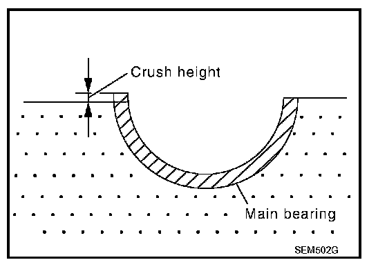
^ When lower cylinder block is removed after being tightened to the specified torque with main bearings installed, the tip end of bearing must protrude. Refer to EM-80, "ASSEMBLY" for the tightening procedure. Disassembly and Assembly
Standard: There must be crush height.
^ If the standard is not met, replace main bearings.
CONNECTING ROD BEARING CRUSH HEIGHT
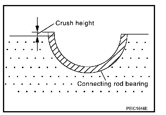
^ When connecting rod bearing cap is removed after being tightened to the specified torque with connecting rod bearings installed, the tip end of bearing must protrude. Refer to EM-80, "ASSEMBLY" for the tightening procedure. Disassembly and Assembly
Standard: There must be crush height.
^ If the standard is not met, replace connecting rod bearings.
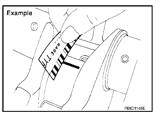
Part 1:
Part 2:
CYLINDER BLOCK