Control Module: Service and Repair
CONTROL VALVE WITH TCMControl Valve with TCM and A/T Fluid Temperature Sensor 2
TM-357 Exploded View:
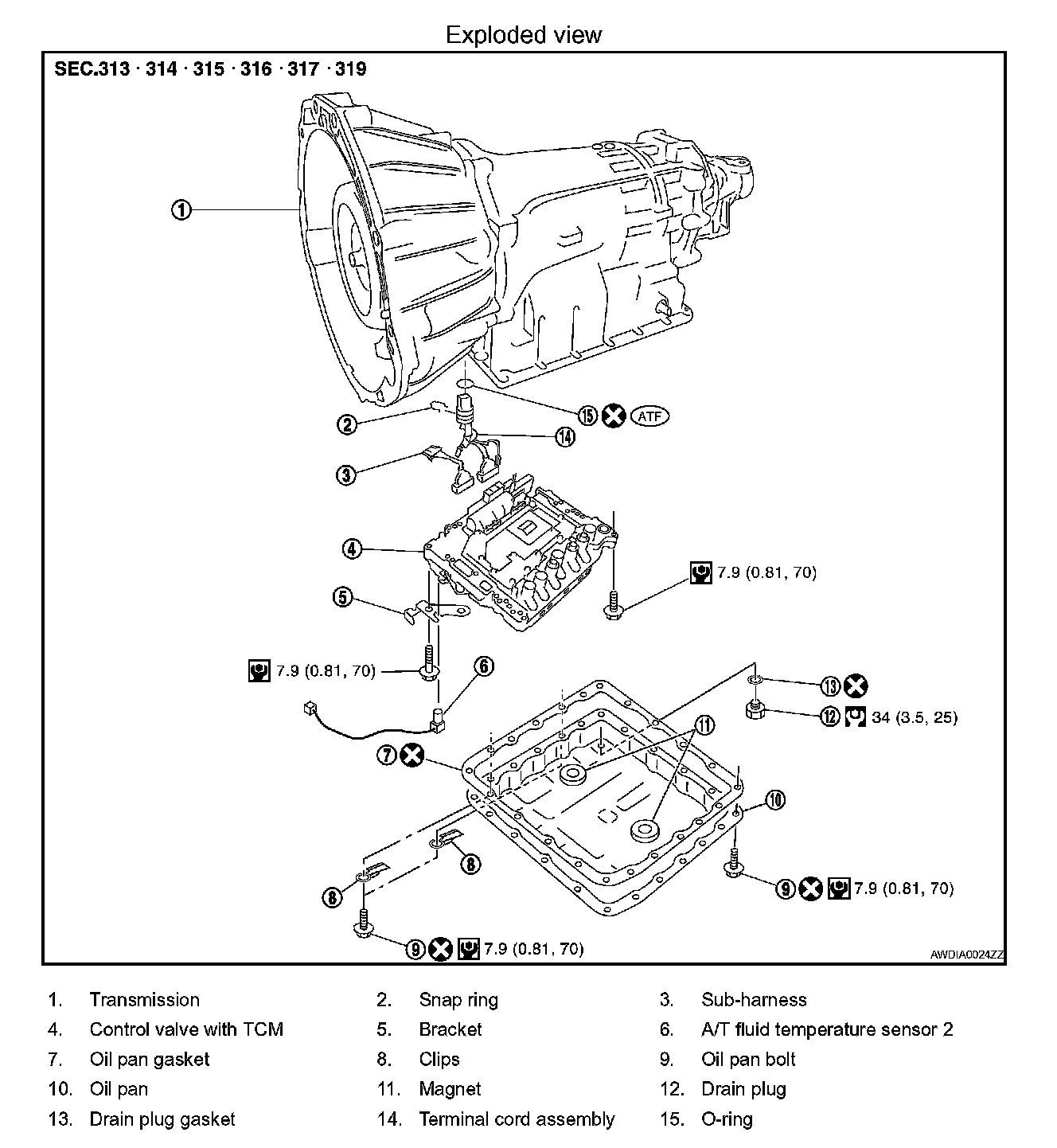
CONTROL VALVE WITH TCM AND A/T FLUID TEMPERATURE SENSOR 2
Removal
1. Disconnect negative battery terminal.
2. Drain A/T fluid. Refer to TM-339, "Checking the A/T Fluid (ATF)". Checking the A/T Fluid (ATF)
3. Disconnect A/T assembly harness connector.
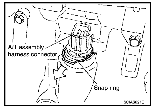
4. Remove snap ring from A/T assembly harness connector.
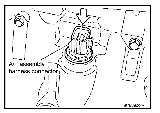
5. Push A/T assembly harness connector.
CAUTION: Do not damage connector.
6. Remove oil pan and oil pan gasket.
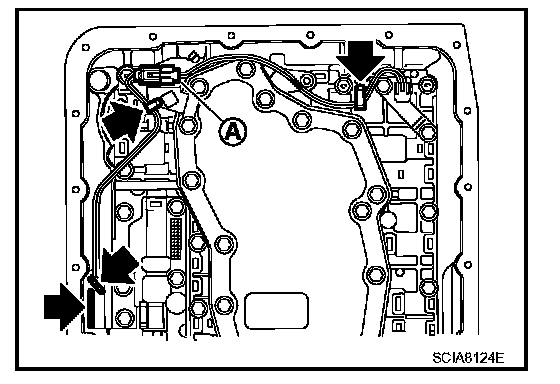
7. Straighten the terminal clips (<---) to free the terminal cord assembly for A/T fluid temperature sensor 2 harness.
^ <---: Terminal clip (4)
8. Disconnect A/T fluid temperature sensor 2 connector (A).
CAUTION: Do not damage connector.
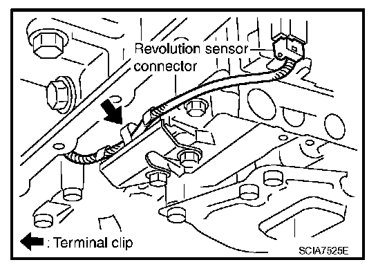
9. Straighten terminal clip to free the revolution sensor harness.
10. Disconnect revolution sensor connector.
CAUTION: Do not damage connector.
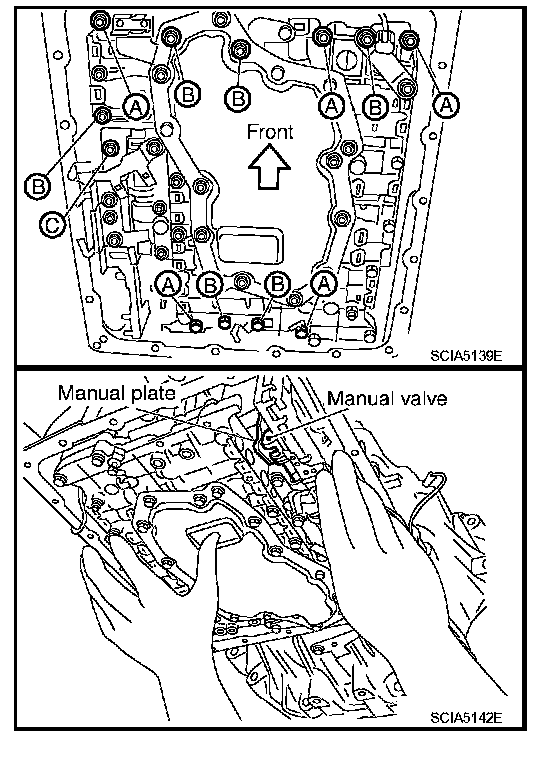
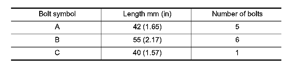
11. Remove bolts (A), (B) and (C) from control valve with TCM.
12. Remove control valve with TCM from transmission case.
CAUTION: When removing, be careful with the manual valve notch and manual plate height. Remove it vertically.
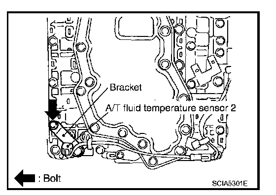
13. Remove A/T fluid temperature sensor 2 with bracket from control valve with TCM.
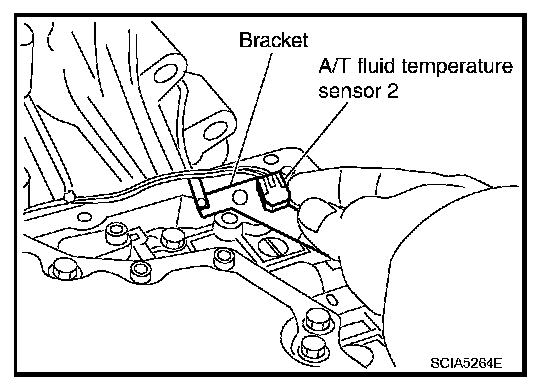
14. Remove bracket from A/T fluid temperature sensor 2.
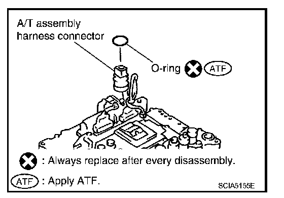
15. Remove O-ring from A/T assembly harness connector.
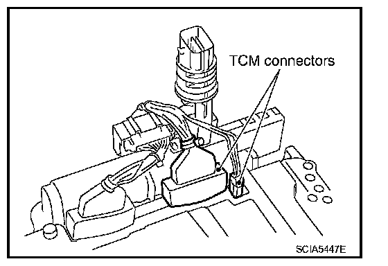
16. Disconnect TCM connectors.
CAUTION: Do not damage connectors.
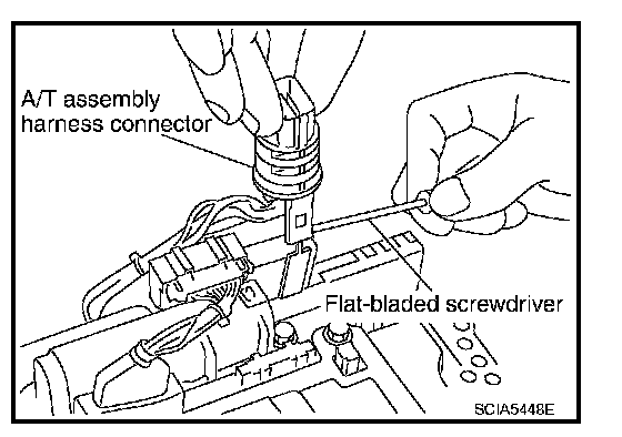
17. Remove A/T assembly harness connector from control valve with TCM using suitable tool.
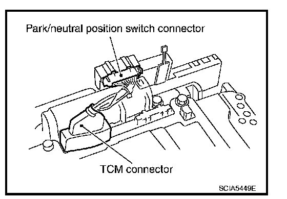
18. Disconnect TCM connector and park/neutral position switch connector
CAUTION: Do not damage connectors.
Installation
CAUTION: After completing installation, check A/T fluid leakage and fluid level. Refer to TM-339, "Checking the A/T Fluid (ATF)". Checking the A/T Fluid (ATF)
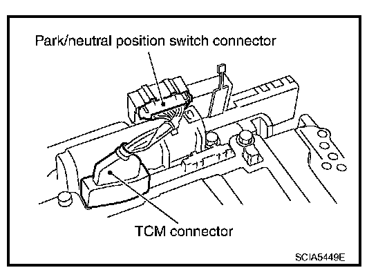
1. Connect TCM connector and park/neutral position switch connector.
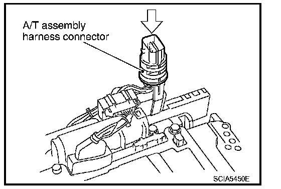
2. Install A/T assembly harness connector to control valve with TCM.
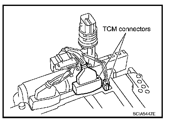
3. Connect TCM connector.
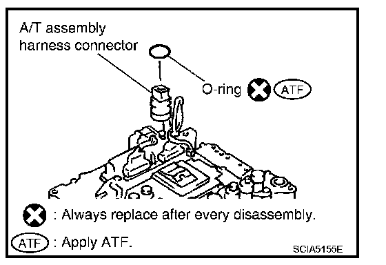
4. Install new O-ring in A/T assembly harness connector.
CAUTION:
^ Do not reuse O-ring.
^ Apply ATF to O-ring.
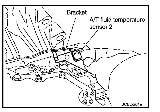
5. Install A/T fluid temperature sensor 2 to bracket.
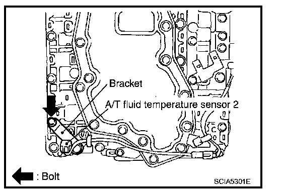
6. Install A/T fluid temperature sensor 2 (with bracket) to control valve with TCM. Tighten A/T fluid temperature sensor 2 bolt to the specified torque. Refer to "Control Valve with TCM and A/T Fluid Temperature Sensor 2".
CAUTION: Adjust bolt hole of bracket to bolt hole of control valve with TCM.
7. Install control valve with TCM in transmission case.
CAUTION:
^ Make sure that turbine revolution sensor is securely installed into turbine revolution sensor hole.
^ Hang down revolution sensor harness toward outside so as not to disturb installation of control valve with TCM.
^ Adjust A/T assembly harness connector of control valve with TCM to terminal hole of transmission case.
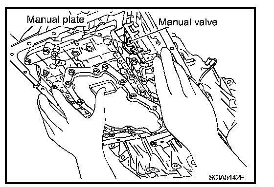
^ Assemble it so that manual valve cutout is engaged with manual plate projection.
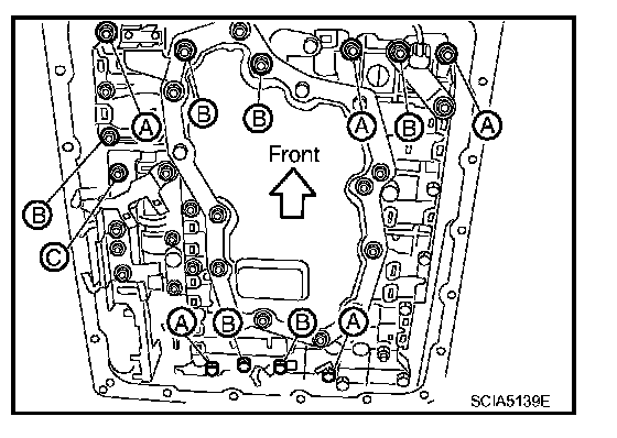
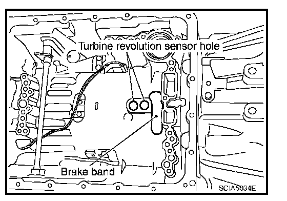
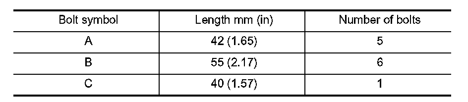
8. Install bolts (A), (B) and (C) in control valve with TCM.
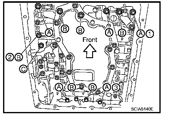
9. Tighten bolt (1), (2) and (3) temporarily to prevent dislocation. After that tighten them in order (1 ---> 2 ---> 3). Then tighten other bolts.
10. Tighten control valve with TCM bolts to the specified torque. Refer to "Control Valve with TCM and A/T Fluid Temperature Sensor 2".
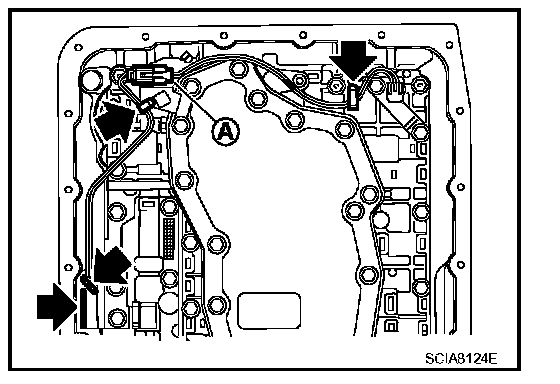
11. Connect A/T fluid temperature sensor 2 connector (A).
12. Securely fasten terminal cord assembly and A/T fluid temperature sensor 2 harness with terminal clips (<---).
^ <---: Terminal clips (4)
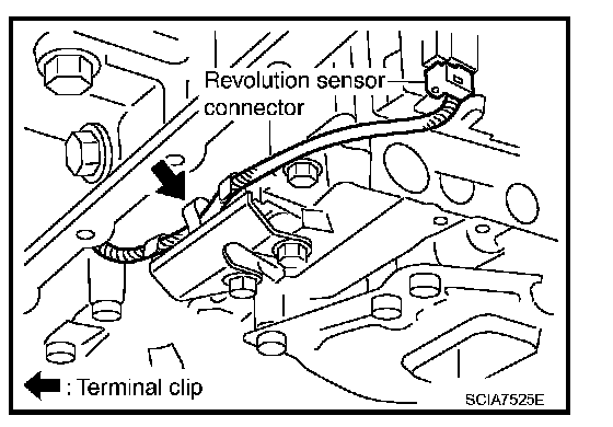
13. Connect revolution sensor connector.
14. Securely fasten revolution sensor harness with terminal clip.
15. Install oil pan to transmission case.
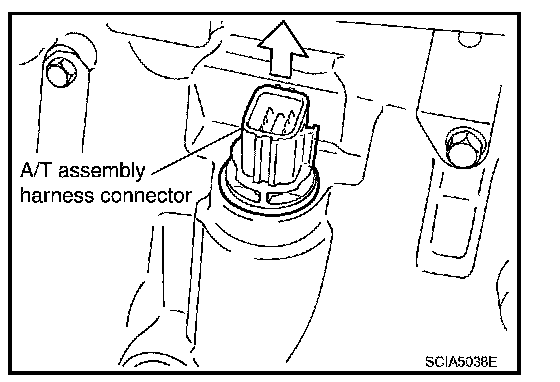
16. Pull up A/T assembly harness connector.
CAUTION: Do not damage connector.
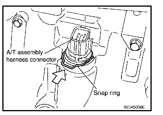
17. Install snap ring to A/T assembly harness connector.
18. Connect A/T assembly harness connector.
19. Connect the negative battery terminal.
20. Refill the A/T with fluid and check the fluid level and for fluid leakage. Refer to TM-339, "Checking the A/T Fluid (ATF)". Checking the A/T Fluid (ATF)
TM-364 Exploded View:
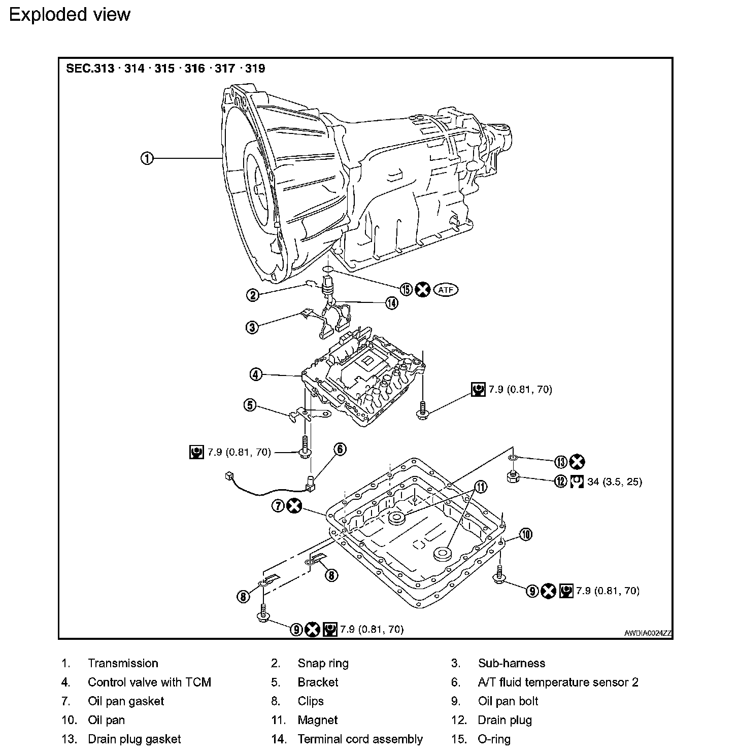
Removal and Installation
CONTROL VALVE WITH TCM REMOVAL AND INSTALLATION
Removal
1. Disconnect negative battery terminal.
2. Drain A/T fluid. Refer to TM-339, "Checking the A/T Fluid (ATF)". Checking the A/T Fluid (ATF)
3. Disconnect A/T assembly harness connector.
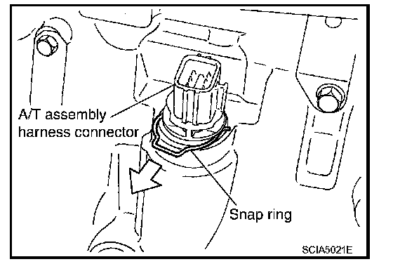
4. Remove snap ring from A/T assembly harness connector.

5. Push A/T assembly harness connector.
CAUTION: Do not damage connector.
6. Remove oil pan and oil pan gasket.
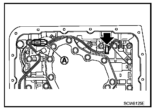
7. Straighten the terminal clip (<---) to free the terminal cord assembly for A/T fluid temperature sensor 2 harness.
8. Disconnect A/T fluid temperature sensor 2 connector (A).
CAUTION: Do not damage connector.
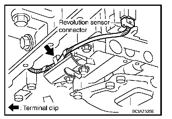
9. Straighten terminal clip to free the revolution sensor harness.
10. Disconnect revolution sensor connector.
CAUTION: Do not damage connector.
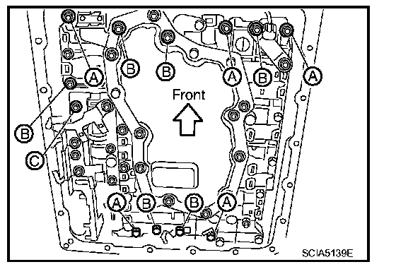
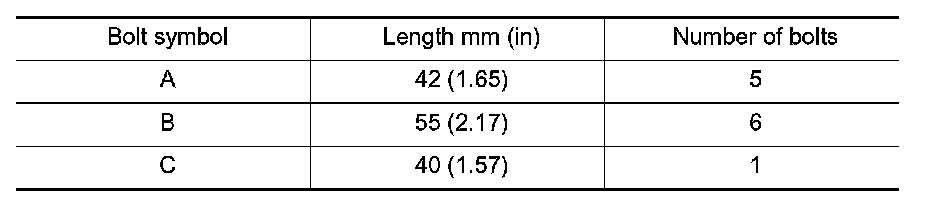
11. Remove bolts (A), (B) and (C) from control valve with TCM.
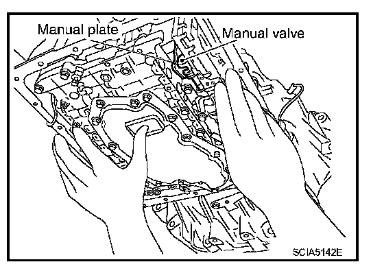
12. Remove control valve with TCM from transmission case.
CAUTION: When removing, be careful with the manual valve notch and manual plate height. Remove it vertically.
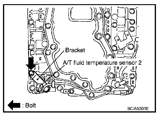
13. Remove A/T fluid temperature sensor 2 with bracket from control valve with TCM.
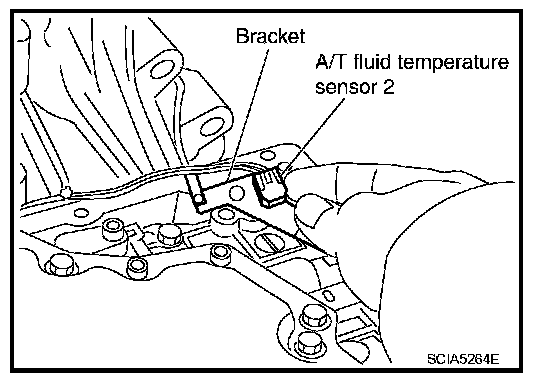
14. Remove bracket from A/T fluid temperature sensor 2.
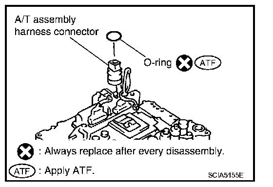
15. Remove O-ring from A/T assembly harness connector.
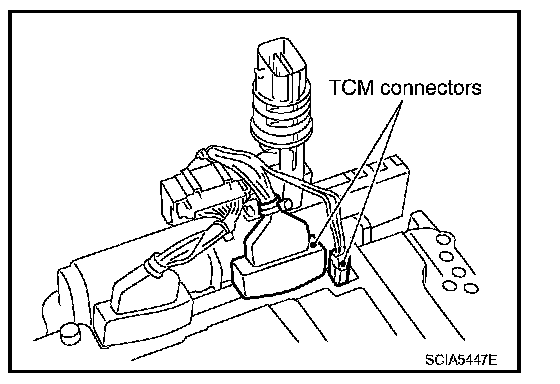
16. Disconnect TCM connectors.
CAUTION: Do not damage connectors.
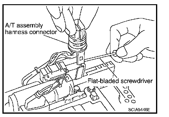
17. Remove A/T assembly harness connector from control valve with TCM using suitable tool.
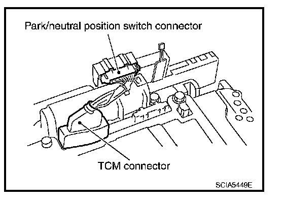
18. Disconnect TCM connector and park/neutral position switch connector
CAUTION: Do not damage connectors.
Installation
CAUTION: After completing installation, check A/T fluid leakage and fluid level. Refer to TM-339, "Checking the A/T Fluid (ATF)". Checking the A/T Fluid (ATF)
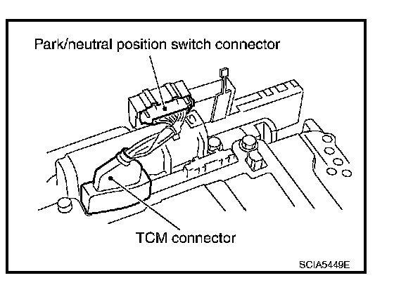
1. Connect TCM connector and park/neutral position switch connector.
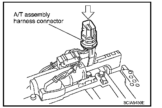
2. Install A/T assembly harness connector to control valve with TCM.
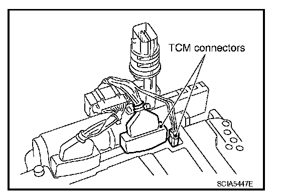
3. Connect TCM connector.
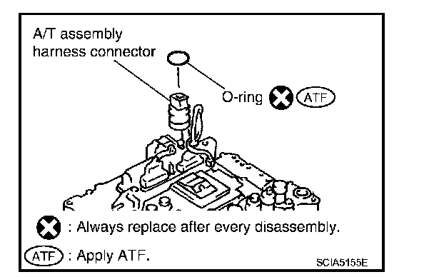
4. Install new O-ring in A/T assembly harness connector.
CAUTION:
^ Do not reuse O-ring.
^ Apply ATF to O-ring.
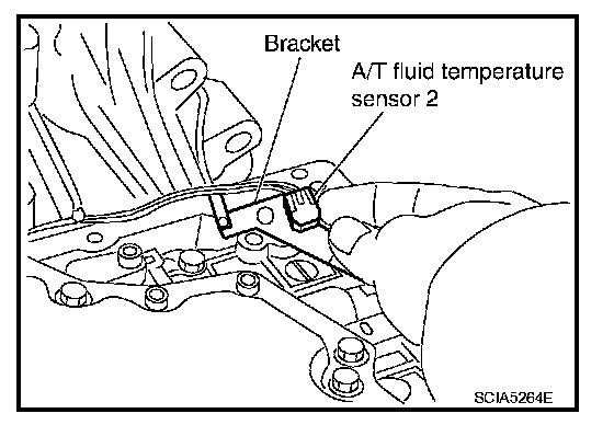
5. Install A/T fluid temperature sensor 2 to bracket.
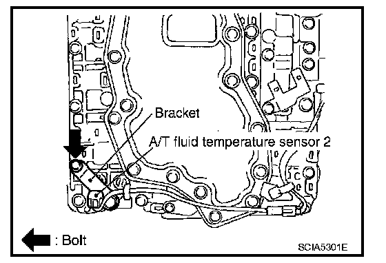
6. Install A/T fluid temperature sensor 2 (with bracket) to control valve with TCM. Tighten A/T fluid temperature sensor 2 bolt to the specified torque. Refer to "Control Valve with TCM and A/T Fluid Temperature Sensor 2".
CAUTION: Adjust bolt hole of bracket to bolt hole of control valve with TCM.
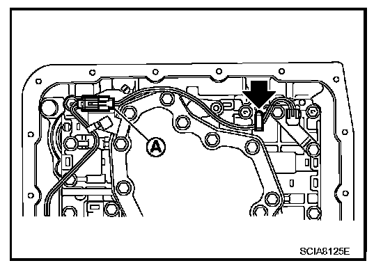
7. Connect A/T fluid temperature sensor 2 connector (A).
8. Securely fasten A/T temperature sensor 2 harness with terminal clip (<---).
9. Install control valve with TCM in transmission case.
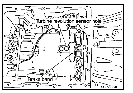
CAUTION:
^ Make sure that turbine revolution sensor is securely installed into turbine revolution sensor hole.
^ Hang down revolution sensor harness toward outside so as not to disturb installation of control valve with TCM.
^ Adjust A/T assembly harness connector of control valve with TCM to terminal hole of transmission case.
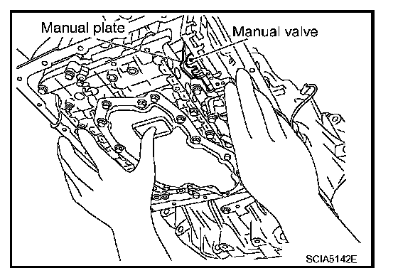
^ Assemble it so that manual valve cutout is engaged with manual plate projection.
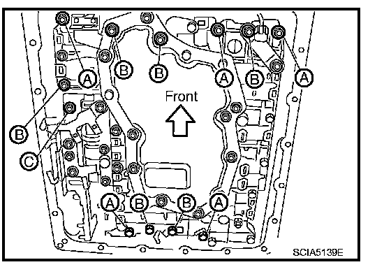
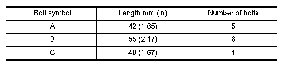
10. Install bolts (A), (B) and (C) in control valve with TCM.

11. Tighten bolt (1), (2) and (3) temporarily to prevent dislocation. After that tighten them in order (1 ---> 2 ---> 3). Then tighten other bolts.
12. Tighten control valve with TCM bolts to the specified torque. Refer to "Control Valve with TCM and A/T Fluid Temperature Sensor 2".
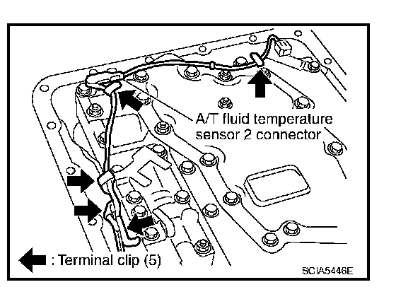
13. Connect A/T fluid temperature sensor 2 connector.
14. Securely fasten terminal cord assembly and A/T fluid temperature sensor 2 harness with terminal clips.
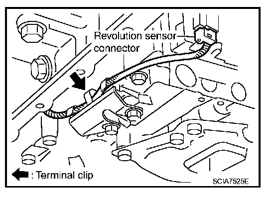
15. Connect revolution sensor connector.
16. Securely fasten revolution sensor harness with terminal clip.
17. Install oil pan to transmission case.
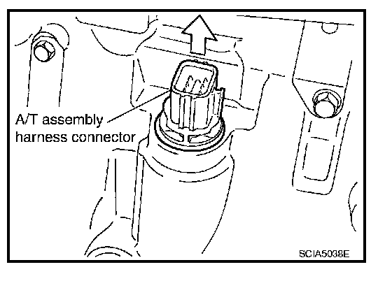
18. Pull up A/T assembly harness connector.
CAUTION: Do not damage connector.
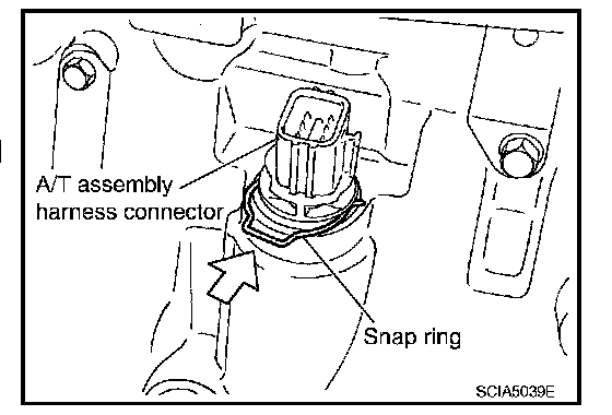
19. Install snap ring to A/T assembly harness connector.
20. Connect A/T assembly harness connector.
21. Connect the negative battery terminal.
22. Refill the A/T with fluid and check the fluid level and for fluid leakage. Refer to TM-339, "Checking the A/T Fluid (ATF)". Checking the A/T Fluid (ATF)