Shift Lock System
SHIFT LOCK SYSTEM
Description
The selector lever cannot be shifted from "P" position to any other position unless the ignition switch is in the
ON position and the brake pedal is depressed.
Component Function Check
1. CHECK CVT SHIFT LOCK OPERATION
1. Turn ignition switch ON.
2. Move selector lever to "P" position.
3. Attempt to shift selector lever to any other position with brake pedal released.
Can selector lever be shifted to any other position?
YES - Go to SEE Diagnosis Procedure.
NO - GO TO 2.
2. CHECK CVT SHIFT LOCK OPERATION
Attempt to shift selector lever to any other position with brake pedal depressed.
Can the selector lever be shifted to any other position?
YES - Inspection End
NO - Go to SEE Diagnosis Procedure.
Diagnosis Procedure
Regarding Wiring Diagram information, CVT Shift Lock System.
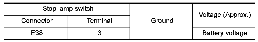
1. CHECK POWER SOURCE (STOP LAMP SWITCH)
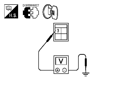
1. Turn ignition switch OFF.
2. Disconnect stop lamp switch connector.
3. Check voltage between stop lamp switch connector E38 terminal 3 and ground.
Is the inspection result normal?
YES - GO TO 2.
NO - Check the following:
- Harness for short or open between fuse block (J/B) and stop lamp switch
- 10A fuse (No. 7, located in fuse block [J/B])
2.CHECK STOP LAMP SWITCH
Check stop lamp switch. SEE Component Inspection (Stop Lamp Switch).
Is the inspection result normal?
YES - GO TO 3.
NO - Replace stop lamp switch. Exploded View.
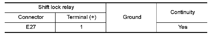
3.CHECK GROUND CIRCUIT (SHIFT LOCK RELAY)
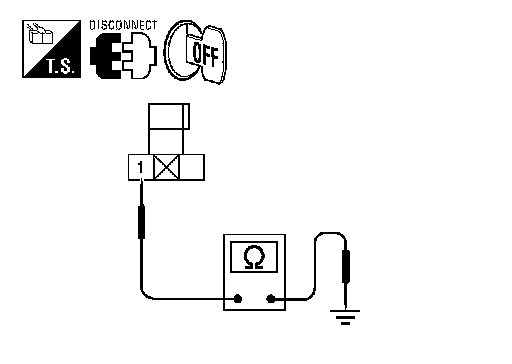
1. Remove shift lock relay.
2. Check continuity between shift lock relay connector E27 terminal 1 and ground.
Is the inspection result normal?
YES - GO TO 4.
NO - Repair or replace damaged parts.
4.CHECK HARNESS BETWEEN SHIFT LOCK RELAY AND STOP LAMP SWITCH FOR OPEN
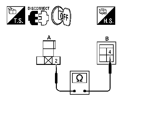
Check continuity between shift lock relay connector E27 (A) terminal 2 and stop lamp switch connector E38 (B) terminal 4.
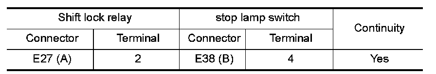
Is the inspection result normal?
YES - GO TO 5.
NO - Repair or replace damaged parts.
5.CHECK HARNESS BETWEEN SHIFT LOCK RELAY AND STOP LAMP SWITCH FOR SHORT CIRCUIT
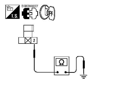
Check continuity between shift lock relay connector E27 terminal 2 and ground.
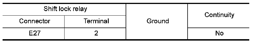
Is the inspection result normal?
YES - GO TO 6.
NO - Repair or replace damaged parts.
6.CHECK POWER SOURCE (SHIFT LOCK RELAY)
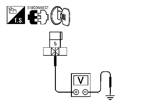
1. Turn ignition switch ON.
2. Check voltage between shift lock relay connector E27 terminal 5 and ground.
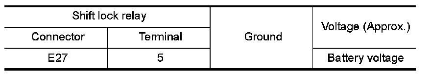
Is the inspection result normal?
YES - GO TO 9.
NO - GO TO 7.
7.CHECK HARNESS BETWEEN FUSE BLOCK (J/B) AND SHIFT LOCK RELAY FOR OPEN
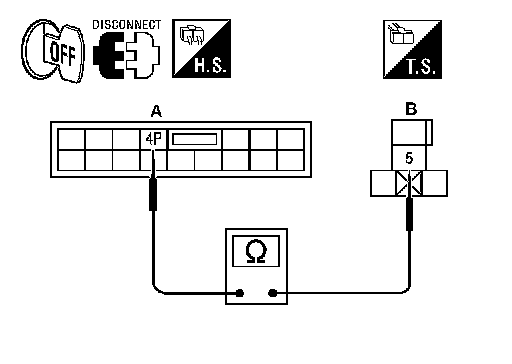
1. Disconnect fuse block (J/B).
2. Check continuity between fuse block (J/B) connector E6 (A) terminal 4P and shift lock relay connector E27 (B) terminal 5.
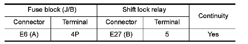
Is the inspection result normal?
YES - GO TO 8.
NO - Repair or replace damaged parts.
8.CHECK HARNESS BETWEEN FUSE BLOCK (J/B) AND SHIFT LOCK RELAY FOR SHORT CIRCUIT
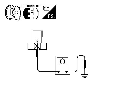
Check continuity between shift lock relay connector E27 terminal 5 and ground.
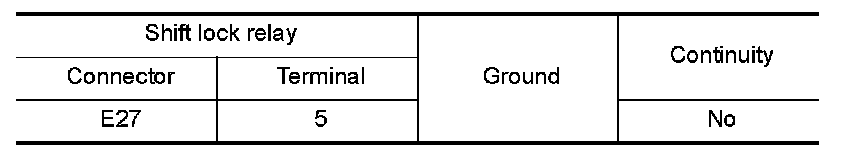
Is the inspection result normal?
YES - GO TO 9.
NO - Check the following. If NG, repair or replace damaged parts.
- 10A (No. 3, located in fuse block [J/B])
- Ignition switch
9.CHECK HARNESS BETWEEN SHIFT LOCK RELAY AND CVT SHIFT SELECTOR FOR OPEN
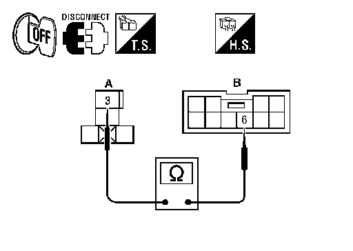
1. Disconnect CVT shift selector connector.
2. Check continuity between shift lock relay connector E27 (A) terminal 3 and CVT shift selector connector M78 (B) terminal 6.
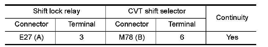
Is the inspection result normal?
YES - GO TO 10.
NO - Repair or replace damaged parts.
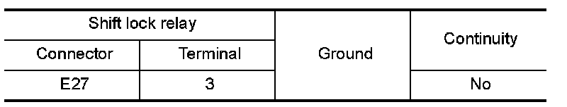
10.CHECK HARNESS BETWEEN SHIFT LOCK RELAY AND CVT SHIFT SELECTOR FOR SHORT CIRCUIT
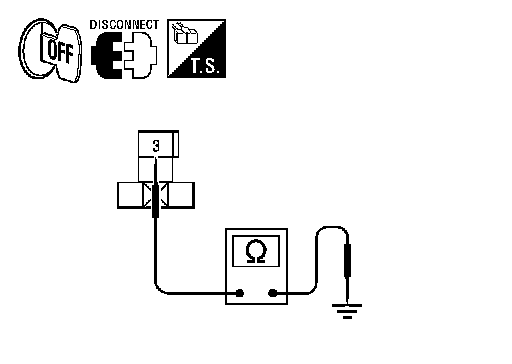
Check continuity between shift lock relay connector E27 terminal 3 and ground.
Is the inspection result normal?
YES - GO TO 11.
NO - Repair or replace damaged parts.
11.CHECK SHIFT LOCK RELAY
Check shift lock relay. SEE Component Inspection (Shift Lock Relay).
Is the inspection result normal?
YES - GO TO 12.
NO - Replace shift lock relay.
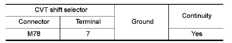
12.CHECK GROUND CIRCUIT (CVT SHIFT SELECTOR)
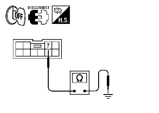
Check continuity between CVT shift selector connector M78 terminal 7 and ground.
Is the inspection result normal?
YES - Replace shift lock solenoid. Exploded View.
NO - Repair or replace damaged parts.
Component Inspection (Stop Lamp Switch)
1.CHECK STOP LAMP SWITCH
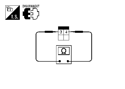
Check continuity between stop lamp switch terminals.
Is the inspection result normal?
YES - Inspection End
NO - Replace stop lamp switch. Exploded View.
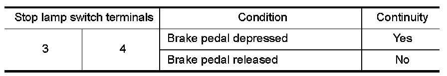
Component Inspection (Shift Lock Relay)
1.CHECK SHIFT LOCK RELAY
1. Apply battery voltage between terminals 2 and 1 of the shift lock relay.
CAUTION:
Connect a fuse between the terminals when applying battery voltage.
2. Check continuity between shift lock relay terminals 5 and 3.
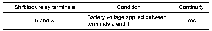
Is the inspection result normal?
YES - Inspection End
NO - Replace shift lock relay.