Chart A-3
CHART A-3 (page 1 of 3)ENGINE CRANKS BUT WON'T RUN (EXCHANGE PROGRAM)
Condition: 2.3L "N" CARLINE (PORT) Engine cranks but won't run, or engine may start, but immediately stops running. Battery condition and engine cranking speed are OK and there is adequate fuel in the tank. Circuit Description:
This engine is equipped with a distributorless ignition system called the "Integrated Direct Ignition" system (IDI). The primary circuit of the "IDI" consists of two separate ignition coils, an "IDI" ignition module and crankshaft sensor as well as the related connecting wires and the EST (electronic spark timing) portion of the ECM. Each secondary circuit consists of the secondary windings of the coil, two connecting metal strips molded into the coil housing, the spark plug boot/connector assemblies and spark plugs.
Test Description: The following numbered steps correspond with the step numbers on the diagnostic chart.
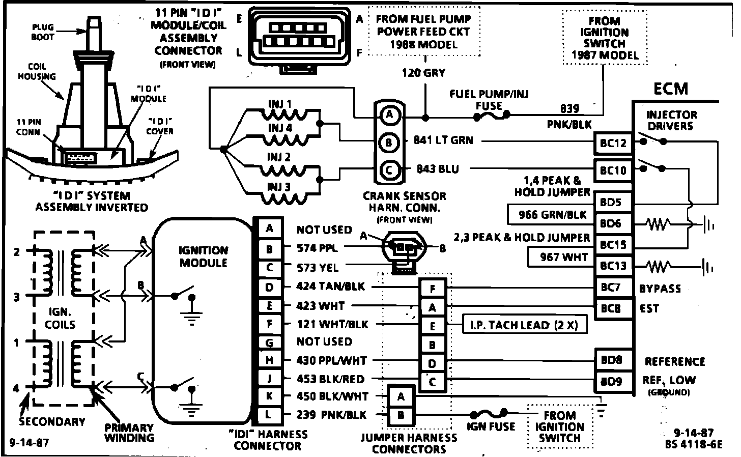
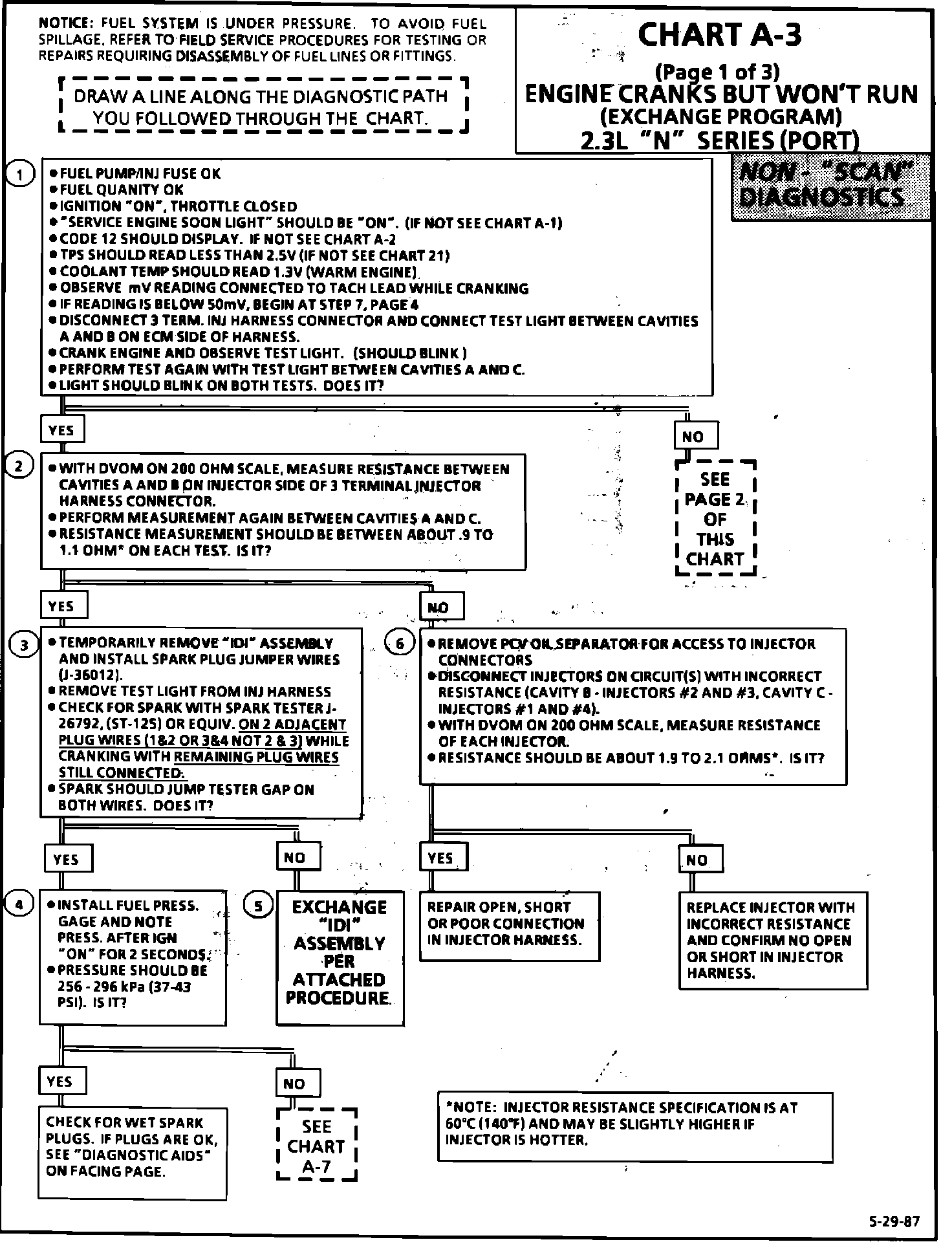
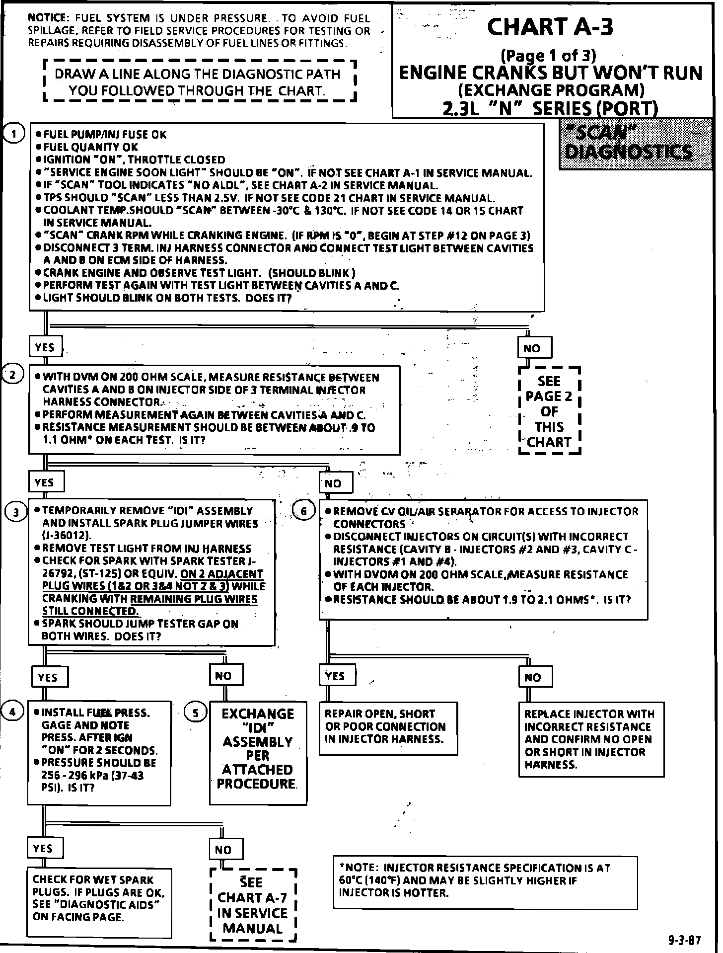
1. This step verifies that "SES" light operation, onboard diagnostics, cranking rpm, TPS and coolant sensor signals are normal. A blinking test light verifies that the ECM is receiving the "IDI" reference signal and attempting to activate the injectors.
2. This step checks injector harness and injectors for opens or shorts without removing CV oil/air separator for access. Measurement should be half that of one injector due to each pair of injectors forming a parallel circuit.
3. By installing spark plug jumper leads and testing for spark on 2 adjacent plug leads (do not use 2 & 3 as they are on the same coil), each ignition coil's ability to produce at least 25,000 volts is verified
4. Checks to see if fuel pump and relay are operating correctly (fuel pump only on 2-3 seconds) and fuel pressure is within proper range.
5. If the no spark condition is caused by harness connections or the harness, the test light will blink. Otherwise, the "IDI" assembly should be exchanged per the attached instructions.
6. This step determines whether harness or injector is cause of incorrect resistance. Nominal injector resistance is 1.9 to 2.1 ohms at 60~C. Resistance will increase at higher temperatures.
Diagnostic Aids:
Check For:
TPS binding or sticking in wide open throttle position or intermittently shorted or open. Water or foreign material in fuel. Low Compression. (Timing chain failure) Verify that only resistor spark plugs are used.
CHART A-3 (page 2 of 3)
ENGINE CRANKS BUT WON'T RUN 2.3L "N" CARLINE (PORT)
Condition: Engine cranks but won't run, or engine may start, but immediately stops running. Battery condition and engine cranking speed are OK and there is adequate fuel in the tank.
Circuit Description: This engine is equipped with distributorless ignition system called the "Integrated Direct Ignition" system (IDI). The primary circuit of the "IDI" consists of two separate ignition coils, an "IDI" ignition module and crankshaft sensor as well as the related connecting wires and the EST (electronic spark timing) portion of the ECM. The secondary circuit consists of the secondary windings of the coils, two connecting metal strips molded into the coil housing, the spark plug boot/connector assemblies and spark plugs.
Test Description: The following numbered steps correspond with the step numbers on the diagnostic chart.
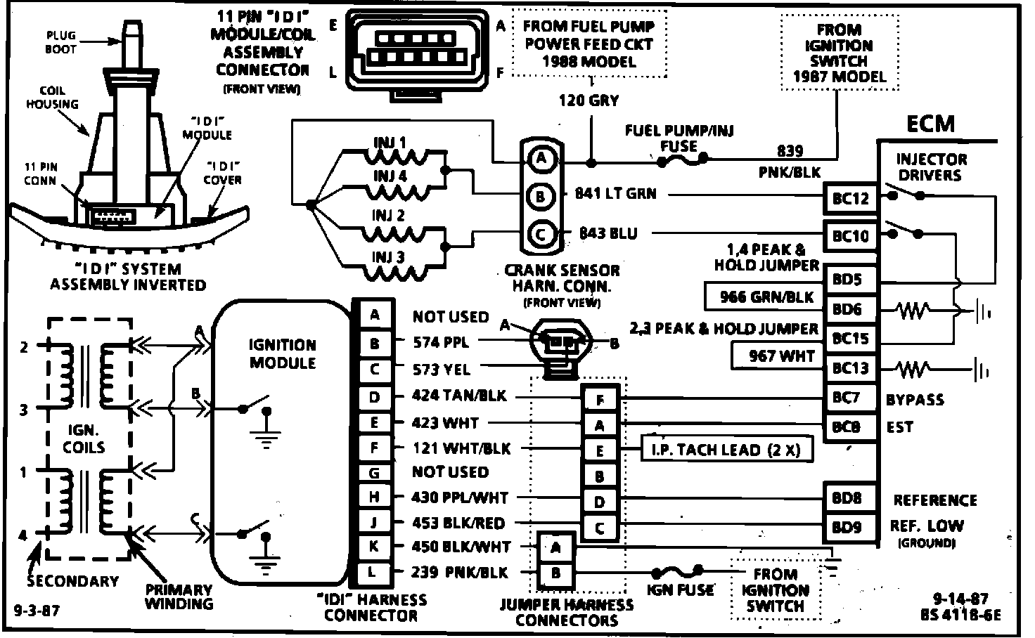
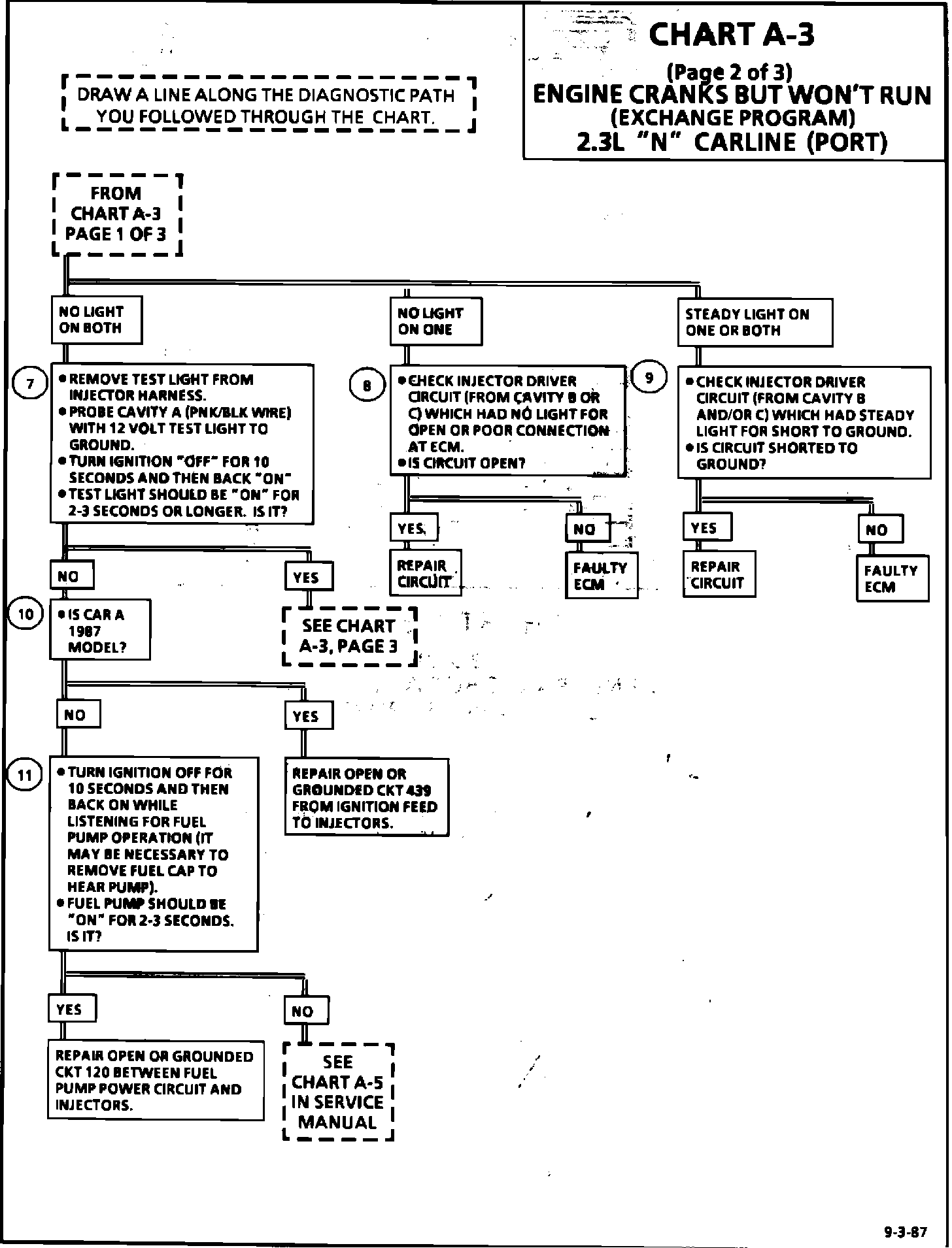
7. Battery voltage should be available at cavity A whenever the fuel pump power feed circuit is switched "ON", for 1988 model cars and whenever the ignition is "ON" for 1987 models. The ECM should switch the fuel pump "ON" for 2-3 seconds after ignition is turned "ON" (and when ECM is receiving ignition reference pulses, as while cranking). The ignition must be turned "OFF" for at least 10 seconds to assure that the ECM powers down and will then switch the fuel pump back "ON" for 2-3 seconds when ignition is turned back on.
8. Light on one circuit only indicates power is available at cavity A, but ground circuit is not being completed on the other circuit. This could be due to open circuit or ECM not switching the injector driver circuit to ground.
9. Steady light indicates ground circuit is always completed and is not being switched. This could be due to short to ground in circuit, or faulty ECM injector driver.
10. 1988 models use the fuel pump power feed circuit to power the injectors, while 1987 models should have power whenever ignition is turned "ON".
11. The fuel pump should be switched "ON" by the ECM for 2-3 seconds after ignition is first turned "ON". It is necessary to turn the ignition "OFF" for at least 10 seconds to assure that the ECM powers down and will then switch the fuel pump back "ON". If the fuel pump operates, but power is not available at injector harness, circuit must be open. If the fuel pump does not operate, CHART A-5 in the service manual should be used to diagnose the cause.
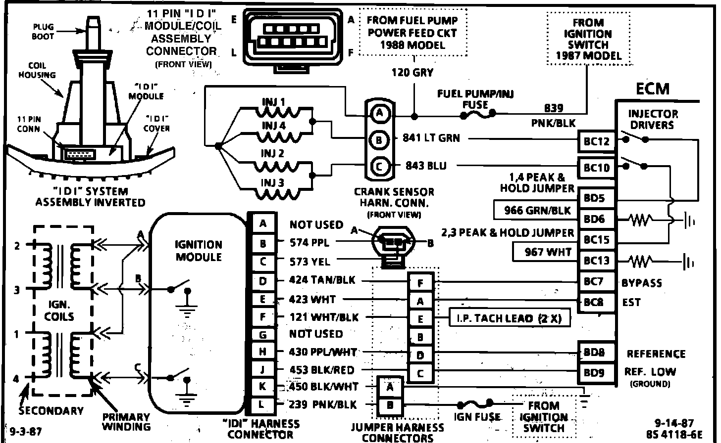
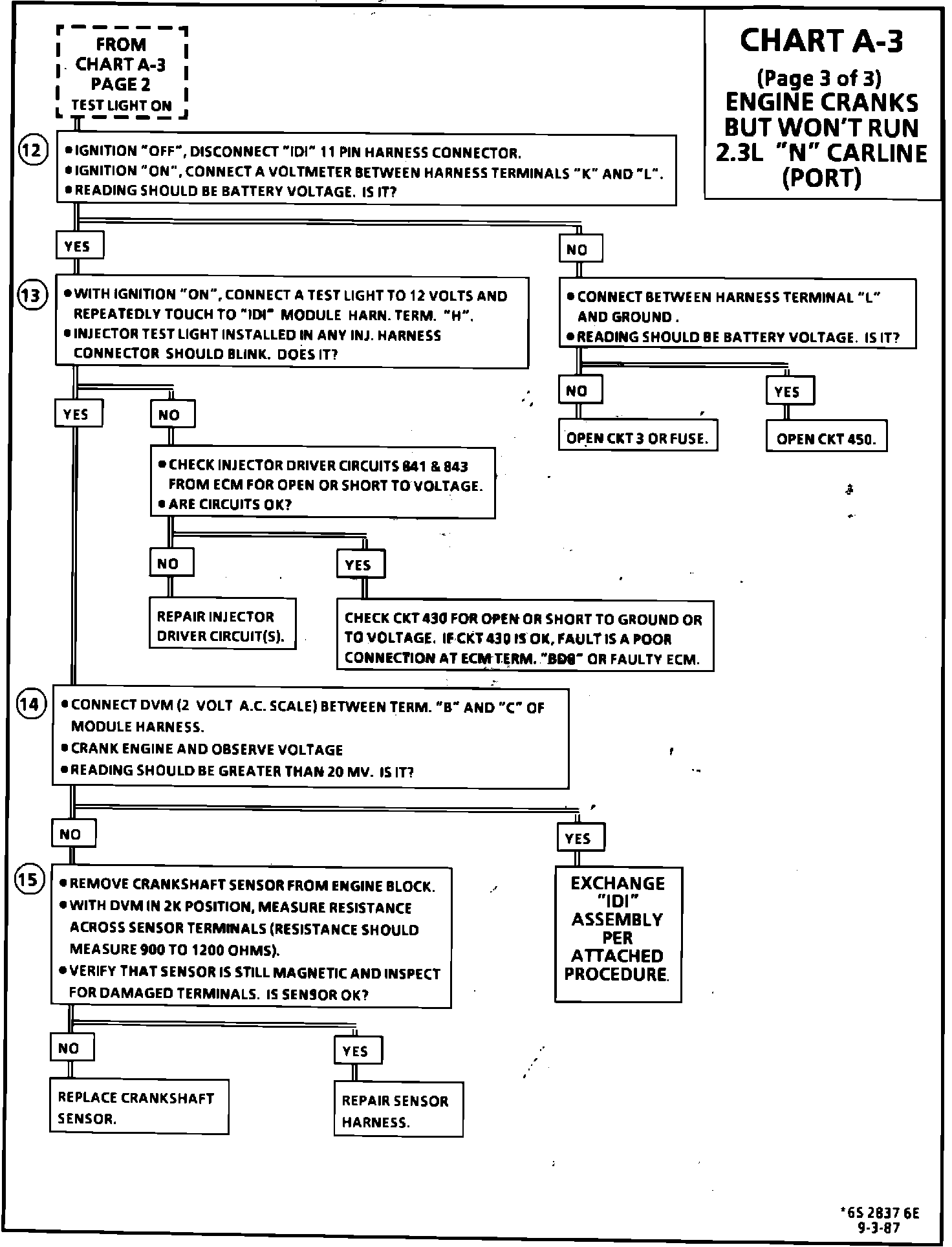
CHART A-3
(Page 3 of 3)
ENGINE CRANKS BUT WON'T RUN 2.3L "N" CARLINE (PORT)
Circuit Description:
The "Integrated Direct Ignition" system (IDI) uses a waste spark method of distribution. In this type of system the ignition module triggers the #1-4 coil pair resulting in both #1 and #4 spark, plugs firing at the same time. #1 cylinder is on the compression stroke at the same time #4 is on the exhaust stroke, resulting in a lower energy requirement to fire #4 spark plug. This leaves the remainder of the high voltage to be used to fire #1 spark plug. On this application, the crank sensor is mounted to, and protrudes through the block to within approx. 0.050" of the crankshaft reluctor. Since the reluctor is a machined portion of the crankshaft and the sensor is mounted in a fixed position on the block, timing adjustments are not possible or necessary.
Test Description: The following numbered steps correspond with the step numbers on the diagnostic chart.
12. Battery voltage should be available at terminal "L" of the "IDI" 11 pin connector and terminal "K" should be a good ground, 13. The test light to 12 volts simulates a reference signal to the ECM which will result in an injector test light blink if CKT 430, the ECM and the injector driver circuit are all functioning properly.
14. The crankshaft sensor should output a voltage as the crankshaft turns. If no voltage is produced, the indication would be a poor sensor connection or faulty sensor.
15. The crank sensor's core is a magnet, therefore it should be magnetized and it's resistance should be within a range of 900 to 1200 OHM's.