Chart C4-M
"INTEGRATED DIRECT IGNITION" MISFIRE DIAGNOSIS
(EXCHANGE PROGRAM)
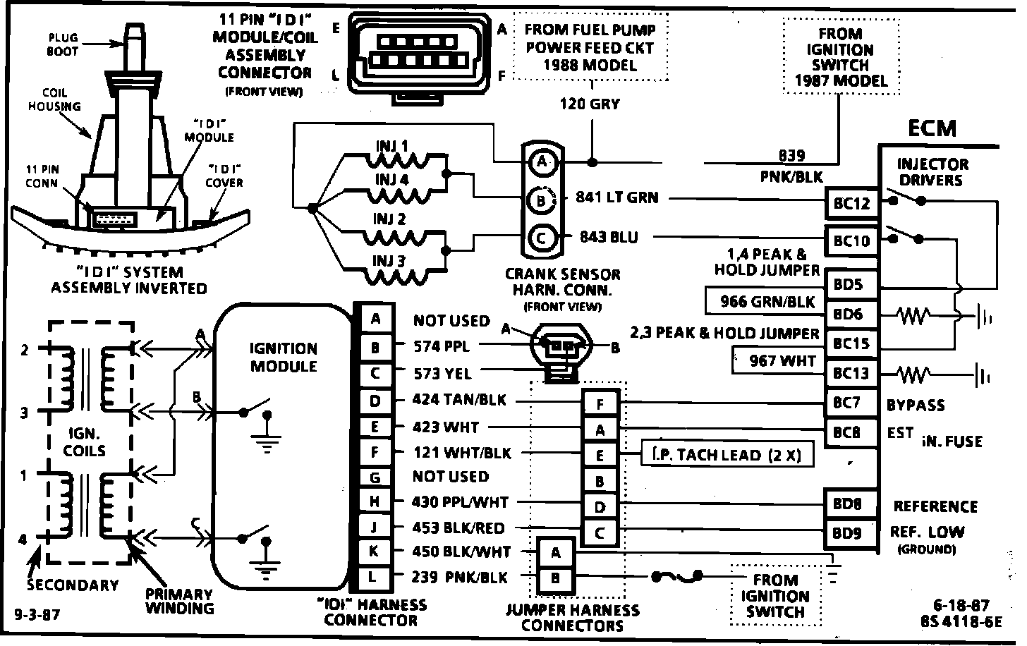
Circuit Description: 2.3L "N" CARLINE (PORT) The "Integrated Direct Ignition" system (IDI) uses a waste spark method of distribution. In this type of system the ignition module triggers the #1-4 coil pair resulting in both #1 and #4 spark plugs firing at the same time. #1 cylinder is on the compression stroke at the same time #4 is on the exhaust stroke; resulting in a lower energy requirement to fire #4 spark plug. This leaves the remainder of the high voltage to be used to fire #1 spark plug. On this application, the crank sensor is mounted to, and protrudes through the block to within approx. .050" of the crankshaft reluctor. Since the reluctor is a machined portion of the crankshaft and the sensor is mounted in a fixed position on the block, timing adjustments are not possible or necessary.
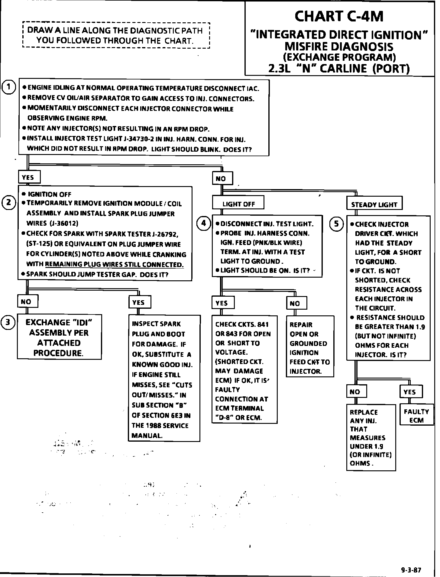
Test Description: The following numbered steps correspond with the step numbers on the diagnostic chart.
1. This checks for equal relative power output between the cylinders. Any injector which when disconnected did not result in an rpm drop approx. equal to the others, is located on the misfiring cylinder.
2. If a plug boot is burned, the other plug on that coil may still fire at idle. This step tests the system's ability to produce at least 25,000 volts at each spark plug.
3. If spark did not jump tester gap for the cylinder which was noted as misfiring, the fault is in the "IDI" and the "IDI" assembly should be exchanged per the attached instructions.
4. Checks for ignition voltage feed to injector and for an open injector driver circuit.
5. An injector driver circuit shorted to ground would result in the test light on steady and possibly a flooded condition which could damage engine. A shorted injector (less than 2 OHMS) could have affected ECM operation.