Cross-Member: Service and Repair
REMOVAL PROCEDURE^ Tools Required:
- J 23742
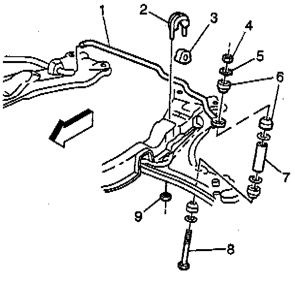
1. Raise and support the vehicle. Allow the suspension to freely hang.
2. If the suspension contact hoist is used:
^ Place jack stands under uni-body frame near the suspension supports.
^ Lower the vehicle slightly so the weight of the vehicle rests on the under the uni-body frame and not on the control arms or the suspension supports.
3. Remove the tire and wheel assembly. Refer to WHEEL REMOVAL
4. Remove the nut attaching the stabilizer link to the stabilizer shaft.
5. Remove the nuts attaching the stabilizer shaft clamp to the suspension support.
NOTICE: Care must be exercised to prevent the drive axle joints from being over-extended. When either end of the shaft is disconnected, over-extension of the joint could result in separation of the internal components and possible joint failure. Drive axle joint protectors should be used any time service is performed on or near drive axles. Failure to observe this can result in interior joint or boot damage, and possible joint failure.
6. Remove the ball joint cotter pin and the nut.
7. Separate the ball joint from the knuckle using J 23742.
NOTICE: Use only the recommended tool for separating the ball joint.
8. Remove the bolts attaching the suspension support to the vehicle.
9. Remove the bolts attaching the control arm to the suspension support.
INSTALLATION PROCEDURE
1. Place the control arm into position and loosely install the bolts attaching the control arm to the suspension support.
2. Place the suspension support into position, guiding the ball joint into the steering knuckle, and loosely install the bolts.
3. Install the nuts attaching the stabilizer shaft to the stabilizer links (6).
Tighten
Tighten the nut to 30 Nm (22 ft. lbs.).
NOTICE: Always use the correct fastener in the proper location. When you replace a fastener, use ONLY the exact part number for that application. The manufacturer will call out those fasteners that require a replacement after removal. The manufacturer will also call out the fasteners that require thread lockers or thread sealant. UNLESS OTHERWISE SPECIFIED, do not use supplemental coatings (paints, greases, or other corrosion inhibitors) on threaded fasteners or fastener joint interfaces. Generally, such coatings adversely affect the fastener torque and joint clamping force, and may damage the fastener. When you install fasteners, use the correct tightening sequence and specifications. Following these instructions can help you avoid damage to parts and systems.
4. Install the nut attaching the ball joint to the steering knuckle.
5. Install the cotter pin.
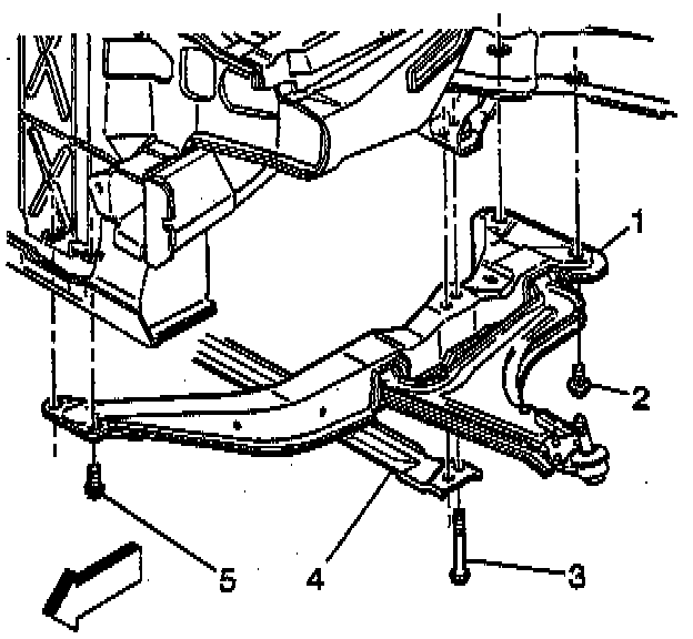
6. Tighten the suspension support bolts - the rear (2) first, the center (3) second, the front (5) third - to specifications.
Tighten
^ Tighten the center bolts first to 120 Nm (89 ft. lbs.).
^ Tighten the front bolts second to 120 Nm (89 ft. lbs.).
^ Tighten the rear bolts third to 120 Nm (89 ft. lbs.).
7. Install the front tire and the wheel assemblies. Refer to WHEEL INSTALLATION.
8. Tighten the control arm attaching bolts.
Tighten
^ Tighten the control arm to the suspension support bolts (front bushing) 100 Nm plus 90° rotation (74 ft. lbs.) plus 90° rotation.
^ Tighten the control arm to the suspension support bolts (rear vertical bushing) 170 Nm (125 ft. lbs.).
9. Check the front wheel alignment. Refer to WHEEL ALIGNMENT SPECIFICATIONS.