Diagnostic System Check
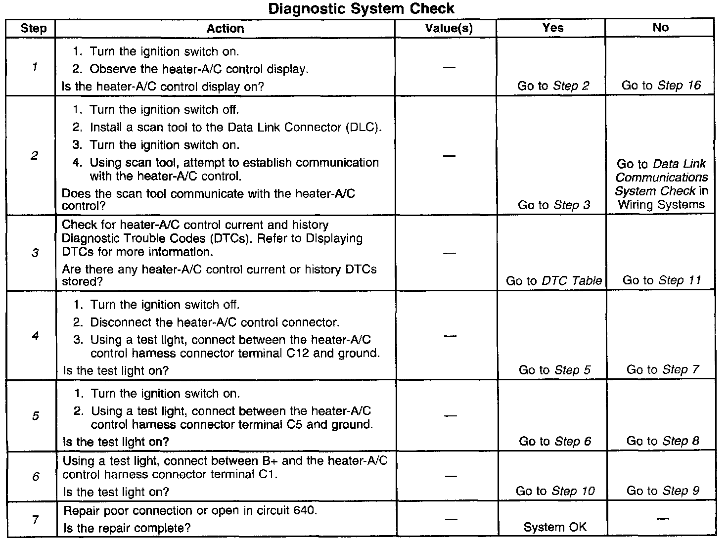
Circuit Description
The heater-A/C control diagnostic system check is an organized approach to identify problems associated with the heater-A/C control. This check must be the starting point for any heater-A/C control complaint, an will direct you to the next logical step in diagnosing the complaint. The heater-A/C control is a very reliable component and is not likely the cause the malfunction. Most system complaints are linked to faulty wiring and connectors, and occasionally to components. Understanding the heater A/C-control and using the diagnostic tables correctly will reduce diagnostic: time and prevent unnecessary parts replacement.
Diagnostic Aids
- The following conditions may result in an intermittent operation of the heater-A/C control with no Diagnostic Trouble Codes (DTCs) stored:
- Any condition which results in the interruption of power to the heater-A/C control.
- Out of range battery or ignition voltage specification. Normal battery or ignition voltage: 9V-16V.
- A loose or damaged ground(s).
- An open or short in the Class 2 serial data link.
- An intermittent failure in the electronic system may be very difficult to detect and accurately diagnose. The heater-A/C control tests for different malfunctions under different vehicle conditions. For this reason, a thorough test drive is often needed in order to repeat a fault condition. If the system malfunction is not repeated during the test drive, a good description of the complaint may be very useful in locating an intermittent fault condition. Faulty electrical connections or wiring cause most intermittent problems. When an intermittent condition is suspected, check the suspected circuits for the following conditions:
- Poor mating of connector halves or backed out terminals.
- Improperly formed or damaged terminals.
- Wire chafing.
- Poor wire-to-terminal connections.
- Dirty wire-to-terminal connections.
- Dirty or corroded terminals.
- Damage to connector bodies.
- Use the J 35616-A whenever a diagnostic procedure requests probing or checking a terminal. Use this adapter in order to ensure that no damage to the terminal will occur and will give an idea of whether contact tension is sufficient.
- If the DTC is a history DTC, the problem may be intermittent. Perform the tests shown while moving the related wiring and connectors. This can often cause the malfunction to occur. Perform a thorough inspection of all related wiring and connectors pertaining to the history DTC stored. Refer to Intermittents and Poor Connections for more information. Intermittent and Poor Conditions
- Exit all the scan tool tests before cycling the ignition switch from the off to the on position unless you are directed otherwise. Follow the operating instructions in the scan tool user manual. Failure to follow these instructions may set DTCs, cause vehicle system malfunctions, set false DTCs, or cause scan tool malfunctions.
- Check all relative fuses (see schematic) for the heater-A/C control. If open, check the circuits which are fed power by these fuses for a short to ground.
- Make sure all relative grounds are clean and tight.
- For heater-A/C control service procedures, refer to Control Assembly Replacement in Instrument Panel, Gauges and Console for more information. Control Assembly
- Check for a broken (or partially broken) wire inside of the insulation which could cause system malfunction but prove good in a continuity/voltage check with a system disconnected. These circuits may be intermittent or resistive when loaded, and if possible, should be checked by monitoring for a voltage drop with the system operational (under load).
- Check for proper installation of the aftermarket electronic equipment which may affect the integrity of other systems.
Test Description
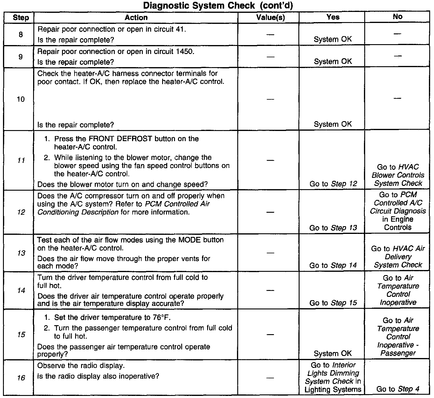
The numbers below refer to the step numbers on the diagnostic table.
1. This test checks power and ground feeds to the heater-A/C control.
2. This test determines if the scan tool communicates with the heater-A/C control.
3. This test checks for Diagnostic Trouble Codes (DTCs) stored in the heater-A/C control.
4. This test checks for an open in circuit 640.
5. This test checks for an open in circuit 41 (BRN).
6. This test checks for an open in circuit 1450 (BLK).
11. This test checks for a problem with the blower controls.
12. This test checks for a problem with the A/C compressor controls.
13. This test checks for a problem with the air flow modes.
14. This test checks for a problem with the driver air temperature control.
15. This test checks for a problem with the passenger air temperature control.
16. This test determines whether the interior lights dimming circuit is not operating correctly or heater-A/C control is faulty.