Pivot and Pulse Switch Assembly
DISASSEMBLY PROCEDURE1. Remove the upper tilt head components. Refer to STEERING COLUMN TILT HEAD ASSEMBLY.
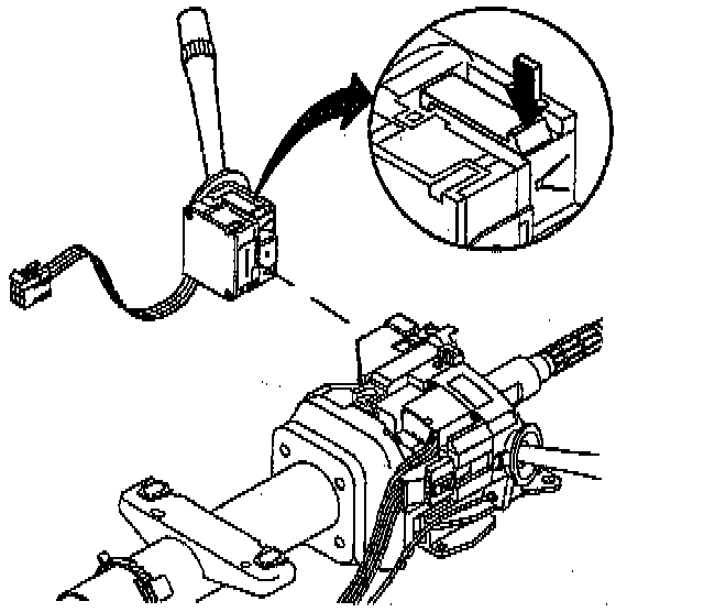
2. Depress the tabs located on the top and bottom of the pivot and pulse switch assembly. Remove the pivot and pulse switch assembly.
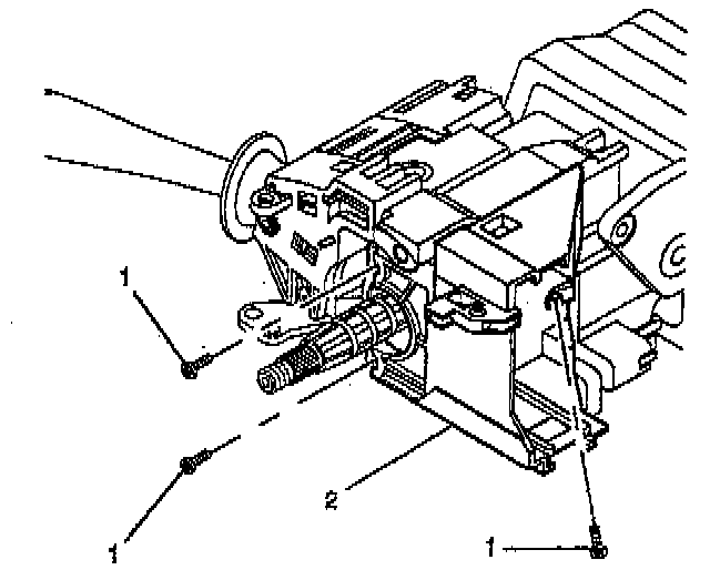
3. Remove 3 pan head tapping screws (1) from the switch mounting bracket (2). Remove the switch mounting bracket (2).
ASSEMBLY PROCEDURE
NOTICE: Always use the correct fastener in the proper location. When you replace a fastener, use ONLY the exact part number for that application. The manufacturer will call out those fasteners that require a replacement after removal. The manufacturer will also call out the fasteners that require thread lockers or thread sealant. UNLESS OTHERWISE SPECIFIED, do not use supplemental coatings (paints, greases, or other corrosion inhibitors) on threaded fasteners or fastener joint interfaces. Generally, such coatings adversely affect the fastener torque and joint clamping force, and may damage the fastener. When you install fasteners, use the correct tightening sequence and specifications. Following these instructions can help you avoid damage to parts and systems.
1. Install the switch mounting bracket (2) and secure by using 3 pan head tapping screws (1).
Tighten
Tighten the screws to 7 Nm (62 lb in).
2. Install pivot and pulse switch assembly to switch mounting bracket.
3. Install the upper tilt head components. Refer to STEERING COLUMN TILT HEAD ASSEMBLY.