Brake Pedal Assy: Service and Repair
REMOVAL PROCEDURE1. Disable the SIR system.
2. Remove the instrument panel assembly.
3. Disconnect the electrical connectors from the switch.
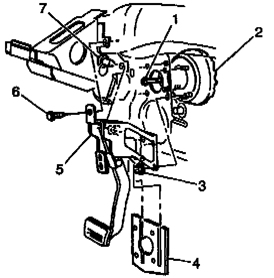
4. Remove the two bolts (7 and 6).
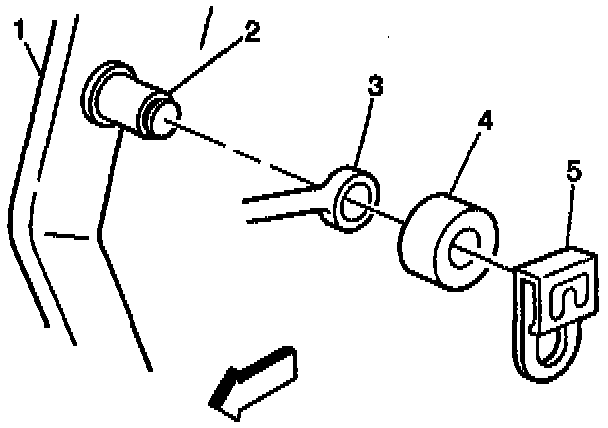
5. Remove the pushrod (3) from the pushrod pin (8).
6. Remove the barrier.
7. Remove the four nuts from the booster studs.
8. Remove the brake pedal assembly (5).
INSTALLATION PROCEDURE
1. Install the brake pedal assembly (5) onto the booster studs.
2. Apply lubricant, or equivalent, to the pushrod pin (8).
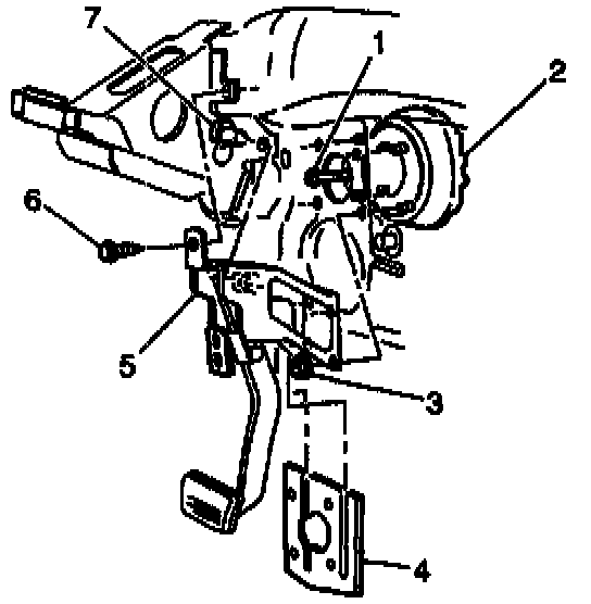
3. Hand start the two bolts (7 and 6) through the brake pedal assembly into the cowl bar and steering column support.
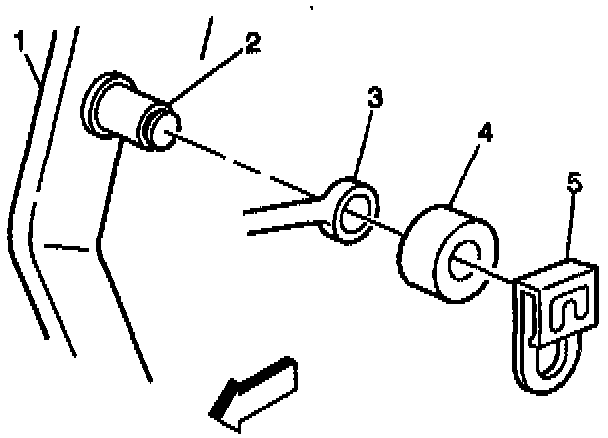
4. Install the pushrod (3) onto the pushrod pin (8).
5. Secure the pushrod with a spacer and a retainer.
NOTICE: Always use the correct fastener in the proper location. When you replace a fastener, use ONLY the exact part number for that application. The manufacturer will call out those fasteners that require a replacement after removal. The manufacturer will also call out the fasteners that require thread lockers or thread sealant. UNLESS OTHERWISE SPECIFIED, do not use supplemental coatings (paints, greases, or other corrosion inhibitors) on threaded fasteners or fastener joint interfaces. Generally, such coatings adversely affect the fastener torque and joint clamping force, and may damage the fastener. When you install fasteners, use the correct tightening sequence and specifications. Following these instructions can help you avoid damage to parts and systems.
6. Install the four nuts onto the booster studs.
^ Tighten the nuts to 21 Nm(15 ft. lbs.).
7. Install the barrier onto the brake pedal assembly.
8. Align with the booster studs.
9. Tighten the bolt (1) first, and then bolt (2).
^ Tighten the bolts to 24 Nm (18 ft. lbs.).
10. Connect the electrical connectors to the switch.
11. Install the instrument panel assembly.
12. Enable the SIR system.