Service Procedure
Figure 1:
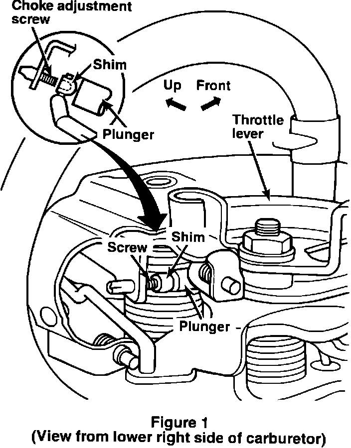
A. Verify Completion of Recall # 419 Service Procedures
1. Remove the air cleaner assembly.
2. Using a flashlight and mirror, check for presence and correct installation of a choke shim on the choke adjusting screw (Figure 1).
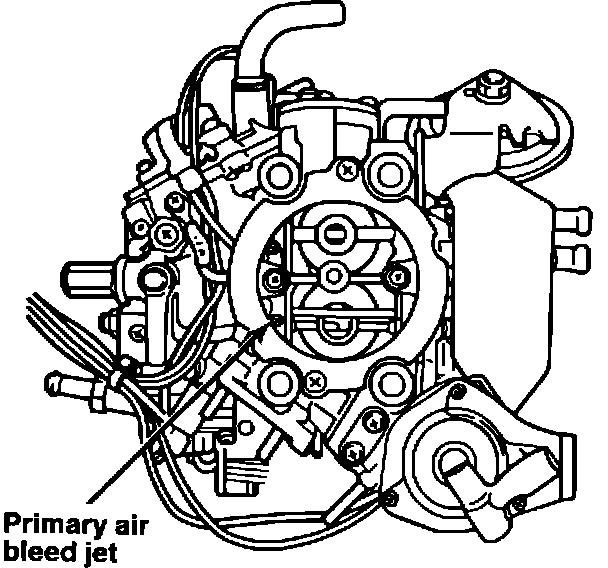
Figure 2:
Service Procedure
A. Verify Completion of Recall # 419 Service Procedures (Continued)
3. Remove the carburetor primary air bleed jet (Figure 2) and verify that a new jet was installed. The new jet will have a "75" stamped on the side.
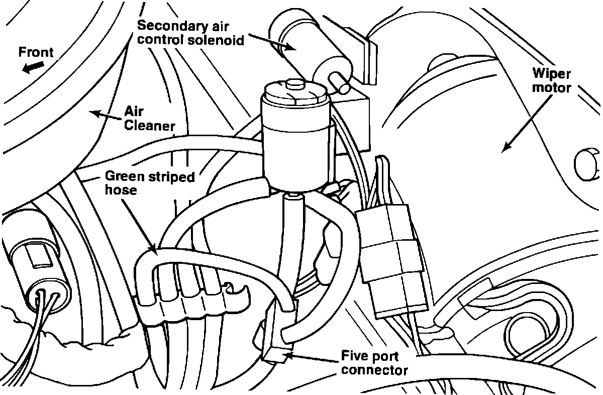
Figure 3:
4. Reinstall the primary air bleed jet.
5. Insure that the vacuum harness was modified by checking to see that the green striped hose has been routed to the five port connector and is no longer connected to the secondary air control solenoid. There should be no hoses connected to the secondary air control solenoid (Figure 3).
Service Procedure
A. Verify Completion of Recall # 419 Service Procedures (Continued)
6. Inspect the carburetor control unit (CCU) harness at the 13-pin CCU connector under the right kick panel in the passenger compartment, to see if the red with blue tracer wire has been cut and taped to the harness.
7. Check the hose routing label to insure that the proper one has been installed (PN MD141717).
NOTE: If any of the above steps have not been completed properly, complete them now following the dealer service instructions from Emissions Recall # 419.
If you did not originally perform the service for Recall # 419 on this vehicle, make the necessary corrections and submit a separate claim for this using the labor operation number and time allowance from Emissions Recall # 419. Then proceed to section B of this (Recall # 473) Service Procedure.
If you originally performed the Recall # 419 service for the vehicle, make the necessary corrections but do not submit a claim for that recall again. Then proceed to section B of this (Recall # 473) Service Procedure.
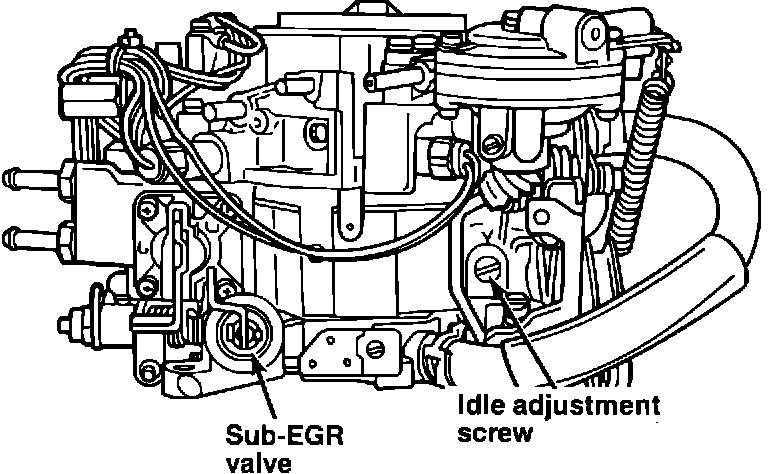
Figure 4:
Service Procedure
B. Readjust the Sub-EGR Valve
1. Disconnect the cooling fan connector.
2. Warm up the engine with accessories off until normal operating temperature is reached.
3. Using the idle adjustment screw (Figure 4), raise the engine idle speed to 1800 RPM.
Figure 5:
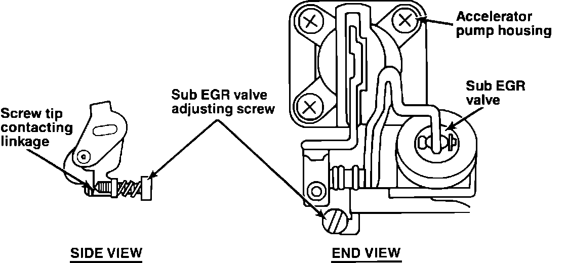
4. Locate the Sub-EGR adjustment screw (Figure 5). Turn the screw counterclockwise until it no longer makes contact with the linkage.
Service Procedure
B. Readjust the Sub-EGR Valve (Continued)
5. Turn the Sub-EGR screw clockwise until it just makes contact with the linkage, then turn it an additional 1/2 turn. Insure that the idle speed is still at 1800 RPM.
NOTE: This must be done visually as you can not feel when screw makes contact with the linkage due to spring tension on the screw.
6. Reset the idle speed to VECI label specification.
7. Reconnect the cooling fan connector.
8. Reinstall the air cleaner assembly.