Front Heater Core
HEATER A/C UNIT RECONDITION
Heater-A/C Housing must be removed from vehicle before performing this operation: Refer to Housing Assembly HVAC/Service and Repair Service and Repair
DISASSEMBLY
Fig. 1:
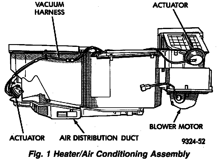
1. Place heater/A/C unit assembly on workbench.
2. Remove one screw retaining the vacuum harness. Feed harness through hole in cover.
3. Remove thirteen screws from top cover and remove cover. Temperature control door will come out with the cover. Remove the nut and lever from the door shaft to remove the temperature door from the cover.
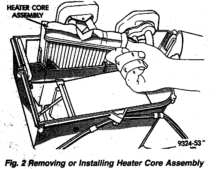
4. Remove screw from heater core tube retaining bracket and lift heater core out of unit (Fig. 2).
Fig. 2:
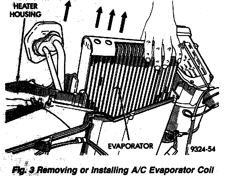
5. Remove A/C evaporator coil out of unit (Fig. 3).
Fig. 3:
6. Disconnect actuator linkage from fresh/recirculation door and vacuum lines from actuator. Loosen two nuts attaching actuator to housing and remove actuator (fig. 4.)
7. Remove four screws attaching fresh/recirculation cover to unit and lift off cover (Fig. 5).
8. Fresh recirculating door may now be removed from its housing.
9. To remove heat defrost door, remove retaining clip from shaft inside the housing. Pull shaft from housing and remove door.
Fig. 4:
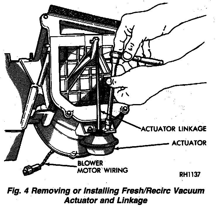
Fig. 5:
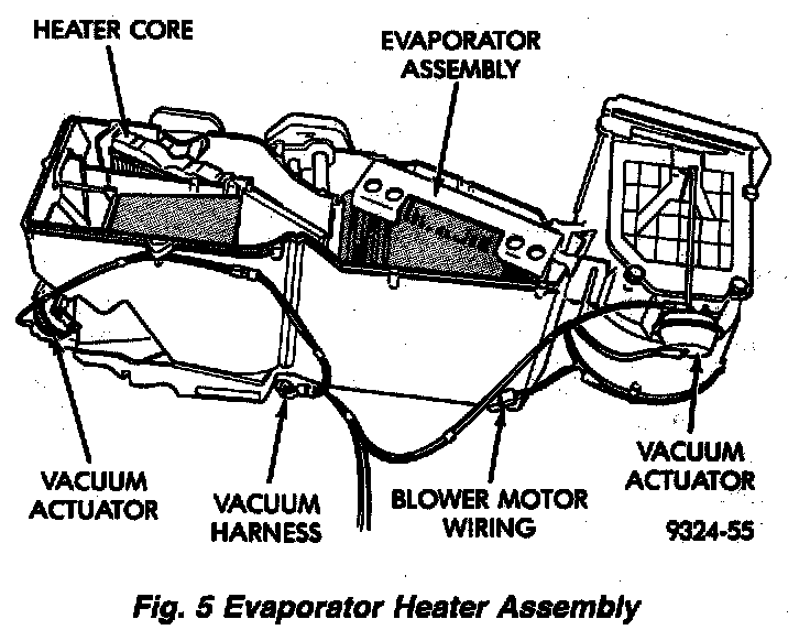
10. To remove mode door, remove retaining clip from shaft inside the housing. Pull the shaft from the housing and remove door.
ASSEMBLY
1. Place evaporator coil into unit.
2. Place heater core into unit and fasten with screws.
3. Reinstall blower wheel onto blower motor shaft and secure with retaining clamp.
4. Feed blower motor wires through hole in housing. Lower blower assembly (rubber seal in place) into housing. Pull wiring grommet into place and install three mounting screws.
5. Install blower motor assembly (five screws) to housing.
6. Install fresh/recirculating door into housing. Install fresh/recirculating cover (four screws). Rotate actuator shaft into door and slide actuator into bracket and tighten two nuts.
7. To install mode door to housing, insert door shaft through housing and door pivot and demister spring. Push on shaft retainer (Fig. 6).
Fig. 6:
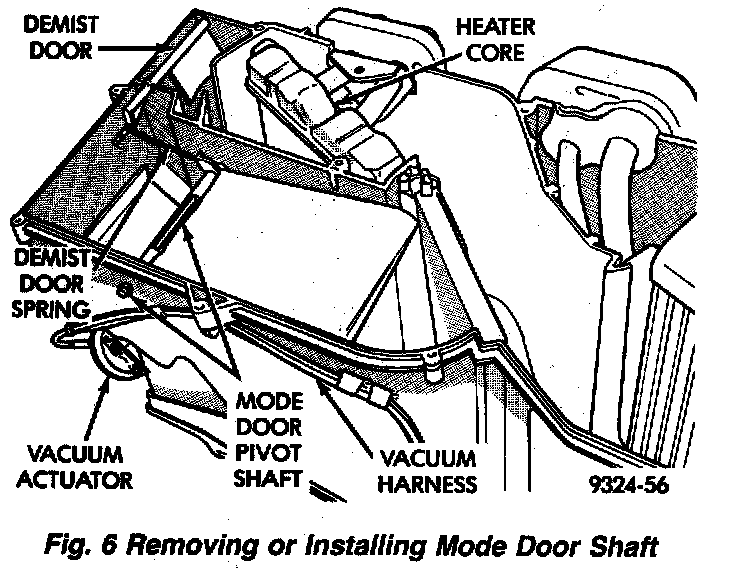
8. To install demister door, connect wire spring to demister door. Insert pivot end of door into hole in housing. Position opposite into slot.
9. To install heat/defrost door, insert door shaft through housing and door pivot. Push on shaft retainer.
10. Install heat distribution duct to bottom of housing with three screws.
11. To install temperature control door, install door shaft into lower pivot in the case housing. Place unit cover over housing while feeding temperature door shaft through cover. If the temperature control door is attached to the cover, feed the door into the housing with the cover. Direct the bottom pivot of the door with your hand through the mode door opening.
12. To install housing cover, line up cover to housing using pilot pins, the temperature door, and screw holes for alignment. Install thirteen screws.
13. Route vacuum harness through holes in cover. Install screw to retain vacuum harness. Make all vacuum hose attachments to vacuum actuators.