Steering Column - Without Key Release
Fig. 19 Fixed steering column exploded view. Rear wheel drive models & 1982---85 Eldorado, Riviera, Seville & Toronado models w/column shift, less key release:

Fig. 20 Fixed steering column exploded view. Front wheel drive models w/column shift, exc. 1982---85 Eldorado, Riviera, Seville, Toronado & models w/key release:
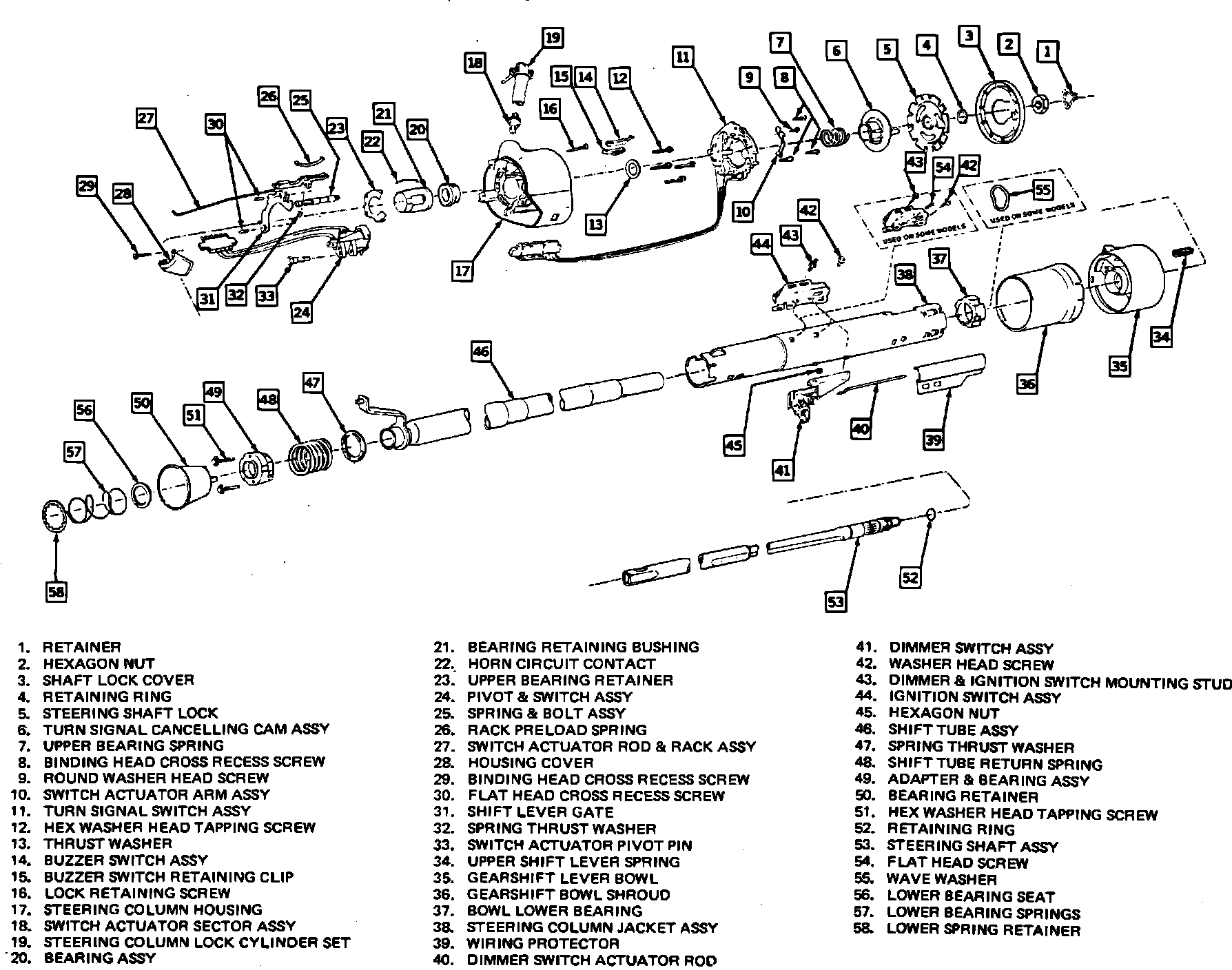
Fig. 21 Fixed steering column exploded view. Models w/floor shift, less key release:
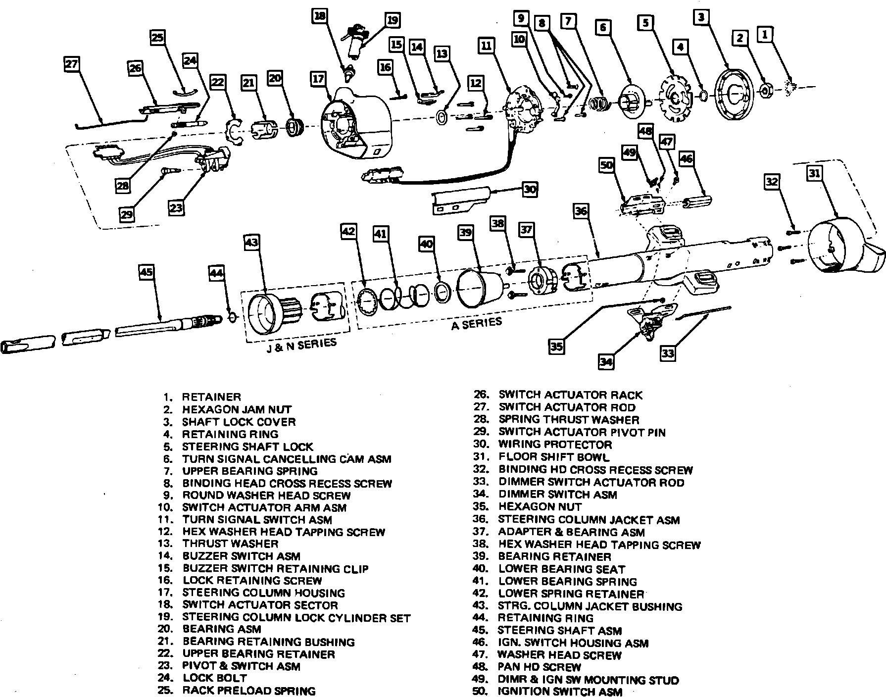
Refer to Figs. 19, 20 and 21 for steering column component identification. Steps 1 through 9 can be performed without column removal.
Disassembly
1. Remove steering wheel, cover screws and cover.
2. Inspect steering shaft to determine type of thread used for steering shaft nut. Metric type shafts can be identified by a groove located in area of steering wheel locating splines, while shaft with American type threads do not have this groove. If shaft has metric type threads, the forcing screw of Lock Plate Compressor Tool J-23653 must be removed and replaced with the metric forcing screw J-23653-4 before installing lock plate compressor tool on steering shaft. Compress lock plate using lock plate compressor tool, then pry snap ring from shaft groove and discard ring. Remove lock plate compressor tool and lock plate.The lock plate is under considerable spring tension, do not attempt to remove lock plate without using lock plate compressor tool. After snap ring has been removed, make sure shaft does not slide out of bottom of column and cause damage to shaft.
3. Remove upper bearing preload spring, horn contact, cancelling cam and thrust washer.
4. Remove turn signal lever. Depress hazard warning knob, remove knob and signal switch.
5. Remove buzzer switch by pulling straight out of housing. This may be done without removing lock cylinder, providing lock cylinder is in ``run'' position.
6. Remove ignition switch and lock cylinder if further service is necessary.
7. Drive out upper shift level pivot pin and remove upper shift lever.
8. Remove upper housing, thrust cup, lock rack, lock bolt, load spring and shift gate.
9. Using a blunt punch, remove sector through lock cylinder hole by pushing firmly on block tooth of sector.
10. Remove shift bowl and shroud from jacket.
Assembly
1. Apply a light coat of grease to all friction surfaces.
2. Install sector in lock cylinder hole over sector shaft with tang end facing outside of hole. Using a blunt punch, press sector over pin.
3. Install shift gate onto housing.
4. Install rack spring in housing from bottom side. Long section should be toward steering wheel and hook onto edge of housing.
5. Assemble bolt to cross-over arm of rack and install rack and lock bolt into housing with teeth facing steering wheel and toward center line of column.
6. Install thrust cup on bottom of hub housing with key of cup aligned with keyway in hub.
7. Install lower bowl bearing in jacket and place wave washer in bowl bearing.
8. Install bowl and rotate to insure proper seating in bearing. Do not install shift lever before installing bowl.
9. Install upper bearing housing assembly on jacket. Bowl should be in ``Park'' position and rack pulled down. Making sure housing is seated on jacket, install screws. Attach housing when properly seated on jacket.
10. Assemble buzzer switch to spring clip with formed end of clip around lower end of switch and spring bowed away from switch. Install switch and spring with contacts toward cylinder bore. Install turn signal switch.
11. With lock cylinder and ignition switch installed and in ``lock'' position, fit actuator rod into switch and assemble to column with two screws.
12. With turn signal switch in ``neutral'' and hazard warning plunger out, install washer, spring, horn contact, cancelling cam and shaft lock plate onto shaft.
13. Using lock plate compressor tool, depress lock plate and install a new snap ring in groove on shaft.
14. Install cover on shaft and install steering wheel.
15. With shift bowl in ``drive'' position install shift lever and adjust neutral-start and back-up light switches.