Assemble
TOOL REQUIREDJ 37096 Flex Plate Holding Tool
J 38196 Rear Main Oil Seal Installer
J 33049 Camshaft Bearing Remover/Installer Set
J 36995 and J 36995-UPD Balance Shaft Bushing Installer
J 41507 Connecting Rod Assembly Guide
J 41349 Rear Main Oil Seal Aligning Tool
J Torque Angle Meter
J 8001 Dial Indicator
J 21465-13 Drive Handle Extension
1. Crankshaft, Bearings, and Bearing Cap
a. Install the crankshaft.
CAUTION: In order to prevent the possibility of cylinder block or crankshaft bearing cap damage, the crankshaft bearing caps are tapped into the cylinder block cavity using a brass, lead, or a leather mallet before the attaching bolts are installed. Do not use attaching bolts to pull the crankshaft bearing caps into the seats. Failure to observe this information may damage a cylinder block or a bearing cap.
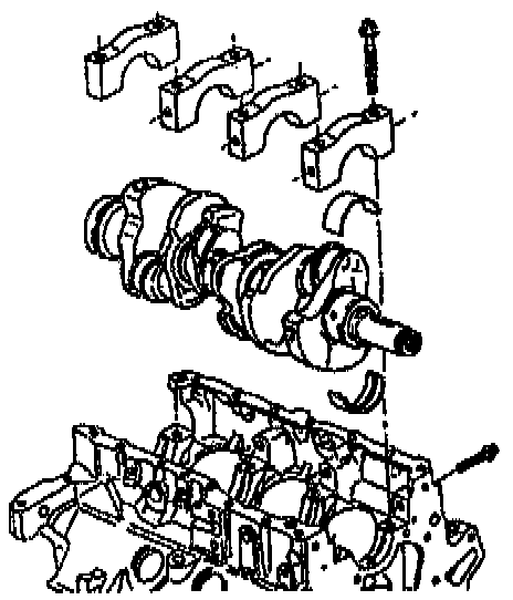
b. Install the main bearing caps. Use GM approved sealer at the Number 4 main bearing cap to the block surface.
CAUTION: This bolt is designed to permanently stretch when tightened. The correct part number fastener must be used to replace this type of fastener. Do not use a bolt that is stronger in this application. If the correct bolt is not used, the parts will not be tightened correctly. The system or the components may be damaged.
c. Install the main bearing cap bolts. Start the main bolts by hand. Ensure that the bottom of the cap is parallel to the bottom of the channel.
^ Tighten all of the caps in equal increments. Do not tighten one cap completely at a time.

^ Tighten the bolts to 70 Nm (52 ft. lbs.) in order to fully seat the caps. Loosen the bolts 360 degrees counterclockwise.
^ Tighten the bolts to 20 Nm (15 ft. lbs.), then 40 Nm (30 ft. lbs.).
^ Use the Torque Angle Meter in order to tighten the bolts in steps: 35 degrees+35 degrees+40 degrees for a total of 110 degrees.
d. Install the side main bolts. Tighten the side main bolts to 15 Nm (11 ft. lbs.). Use the Torque Angle Meter in order to tighten the bolts an additional 45 degrees.
e. Install the connecting rod bearing inserts.
f. Install the connecting rod cap bolts. Tighten the connecting rod cap bolts to 27 Nm (20 ft. lbs.). Use the Torque Angle Meter in order to tighten the bolts an additional 50 degrees.
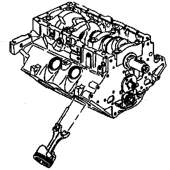
2. Piston, Connecting Rod, and Bearing
a. Position the crankshaft to the location of the connecting rod that is being installed. This will aid in the installation of the connecting rod assembly.
b. Lubricate the cylinder with oil.
c. Install the connecting rod bearing.
d. Lubricate the bearing surface with clean engine oil.
e. Install the Connecting Rod Guide to the connecting rod. Securely hand tighten the tool to the connecting rod.
f. Install the Piston Ring Compressor to the piston.
CAUTION: Guide the lower connecting rod end carefully to avoid damaging the crankshaft journal.
g. Use the Piston Ring Compressor in order to install the piston and connecting rod assembly. Make sure that the ridge(s) are toward the front of the engine.
h. Use the Connecting Rod Guide in order to pull the connecting rod into place.
i. Remove the Connecting Rod Guide.
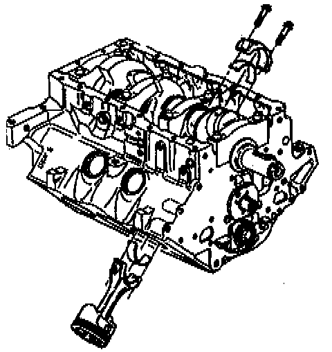
j. Install the connecting rod cap.
CAUTION: This bolt is designed to permanently stretch when tightened. The correct part number fastener must be used to replace this type of fastener. Do not use a bolt that is stronger in this application. If the correct bolt is not used, the parts will not be tightened correctly. The system or the components may be damaged.
k. Install the connecting rod bolts. Tighten the connecting rod bolts to 27 Nm (20 ft. lbs.) +50 degrees using the Torque Angle Meter.
l. Pry the connecting rod back and forth and check for binding. If necessary loosen and retighten the bearing cap.
m. Measure the connecting rod side clearance.
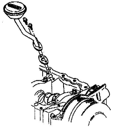
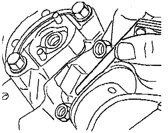
3. Oil Pump Pipe and Screen Assembly
a. Install the oil pump screen gasket.
b. Install the oil pump screen.
c. Install the oil pump screen bolts. Tighten the bolts to 15 Nm (11 ft. lbs.).
4. Oil Pan
a. Install the oil pan gasket to the oil pan flange.
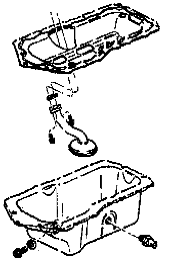
b. Install the oil pan.
c. Install the oil pan bolts. Tighten the bolts to 14 Nm (125 inch lbs.).
CAUTION: Install the oil level sensor, located in the oil pan, after the oil pan is installed. The sensor may be damaged if the oil level sensor is installed first.
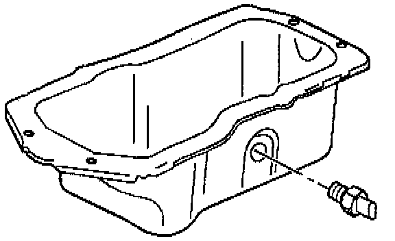
d. Install the oil level sensor.
5. Crankshaft Rear Main Oil Seal Housing
a. Ensure that the oil seal is removed from the housing.
b. Clean the gasket from the housing.
CAUTION: Do not use sealers or adhesives on rear main oil seal housing gasket. Use of sealers or adhesives on this gasket may cause oil leaks.
c. Install the gasket over the housing bolts in order to align the gasket.
CAUTION: Sealability of the rear main oil seal depends on the correct alignment of the rear main oil seal housing and the oil pan. Incorrect alignment may cause oil leaks.
NOTE: The plastic inserts in the housing are used to aid assembly only. The inserts are not required for service.
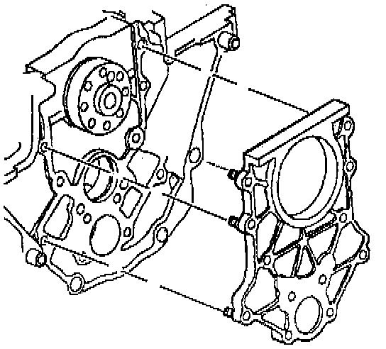
d. Install the housing. Finger tighten the bolts in order to hold the housing in place. Ensure that the gasket is not higher than the housing.
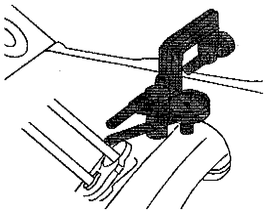
e. Wipe a thin film of oil on both sides of the Rear Main Oil Seal Aligning Tool in order to aid in the installation and removal from the crankshaft.
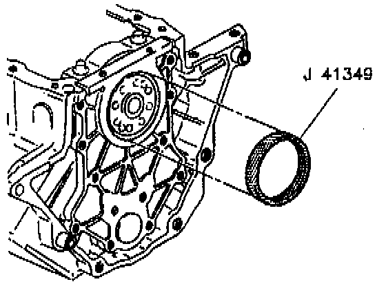
f. Install the Rear Main Oil Seal Aligning Tool over the crankshaft. Twist the tool in order to aid in sliding the tool over the crankshaft.
g. Place a straight edge on the cylinder block oil pan flange and the housing flange. Use a feeler gage in order to ensure that there is no more than 0.004 inch step on each side. Rotate the housing in order to make the step equal on each side. Replace the housing if rotation does not make the step equal.
h. Tighten the housing bolts. Tighten the bolts to 15 Nm (11 ft. lbs.). Use the Torque Angle Meter in order to tighten the bolt an additional 50 degrees.
i. Remove the Rear Main Oil Seal Aligning Tool.
j. Recheck the step height on each side in order to ensure that the housing did not move while tightening the bolts. If the step height is beyond specification, reinstall the housing and measure the step again. Replace the housing if the clearance is still excessive.
6. Crankshaft Rear Main Oil Seal
a. Apply engine oil to the inside diameter and the outside diameter of the new seal.
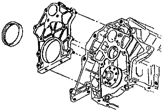
b. Slide the new seal over the mandrel until the back of the seal bottoms squarely against the collar of the tool.
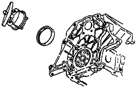
c. Use the following procedure in order to install the seal:
^ Attach the Rear Main Oil Seal Installer to the crankshaft by hand or tighten attaching screws to 5 Nm (54 inch lbs.).
^ Turn the T handle of the Rear Main Oil Seal Installer so that the collar pushes the seal into the bore. Turn the handle until the collar is tight against the case. Ensure that the seal is seated properly.
^ Loosen the T handle of the Rear Main Oil Seal Installer until it comes to a stop.
^ Remove the attaching screws.
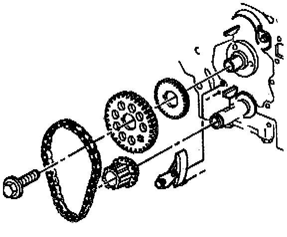
7. Balance Shaft
a. Ensure that no gasket material remains on the rear main oil seal housing.
b. Dip the bushing in clean engine oil.
NOTE: The Balance Shaft Bushing Installer ensures that the rear bushing is installed to the correct depth. The bushing is properly installed when the Balance Shaft Bushing Installer fully contacts the balance shaft bore or the cylinder block/transaxle mounting flange.
c. Use the balance shaft bushing installers in order to install the balance shaft rear bushing.
d. Remove the Balance Shaft Bushing Installer.
e. Dip the front balance shaft bearing into clean engine oil.
f. Use the Torque Angle Meter and the Balance Shaft Installer in order to install the balance shaft into the block.
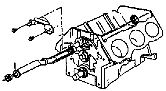
g. Temporarily install the balance shaft bearing retainer. Temporarily install the balance shaft bearing retainer bolts.
h. Install the balance shaft drive gear.
CAUTION: This bolt is designed to permanently stretch when tightened. The correct part number fastener must be used to replace this type of fastener. Do not use a bolt that is stronger in this application. If the correct bolt is not used, the parts will not be tightened correctly. The system or the components may be damaged.
i. Install the balance shaft drive gear bolt. Tighten the bolt to 22 Nm (16 ft. lbs.). Use the Torque Angle Meter in order to tighten the bolt an additional 70 degrees.
j. Install the rear main oil seal housing.
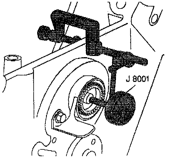
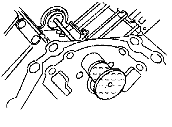
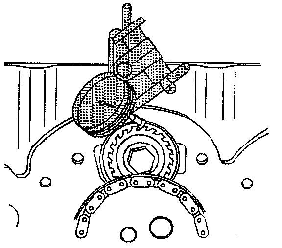
k. Measure the balance shaft end play. End play must not exceed 0.028 mm (0.008 inches).
l. Measure the balance shaft radial play at the rear. Radial play must be between 0.0127-0.119 mm (0.0005-0.0047 inches).
m. Temporarily install the camshaft sprocket.
n. Turn the camshaft so that the timing mark on the camshaft sprocket is straight down.
o. Remove the camshaft sprocket and camshaft gear.
p. Turn the balance shaft so that the timing mark on the gear points straight down.
q. Install the camshaft gear. Align the marks on the balance shaft gear and the camshaft gear. Do this by turning the balance shaft.
r. Turn the crankshaft so that the number one piston is at top dead center.
s. Install the timing chain.
t. Install the camshaft sprocket.
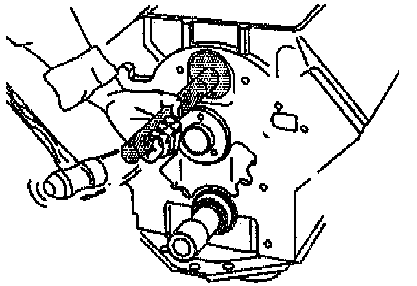
u. Measure gear lash at four places. Measure every 1/4 turn. Gear lash must be between 0.050-0.127 mm (0.002-0.005 inches).
v. Install the balance shaft retainer.
w. Install the balance shaft retainer bolts. Tighten the bolts to 30 Nm (22 ft. lbs.).
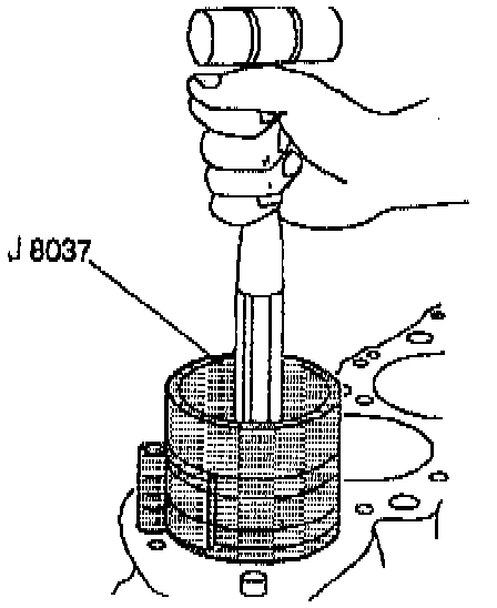
8. Camshaft Bearing
a. Select the camshaft bearings.
b. Use the following procedure in order to install the camshaft bearings:
^ Assemble the Camshaft Bearing Installer according to the manufacturer's instructions.
^ Place the bearing on the tool.
^ Index the bearing oil holes with the cylinder block oil passages.
9. Camshaft
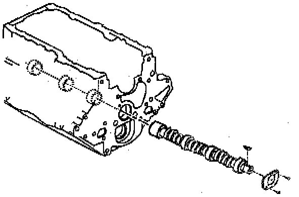
a. Coat the camshaft with prelude GM P/N 12345507 or the equivalent.
b. Install the camshaft.
c. Install the camshaft thrust plate.
d. Install the thrust plate screws. Tighten the screws to 15 Nm (11 ft. lbs.).
10. Timing Chain and Sprockets
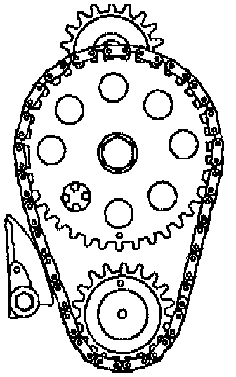
a. Assemble the timing chain on the sprockets. Ensure that the timing marks are in the closest together position.
b. Install the timing chain and the crankshaft sprocket.
c. Install the camshaft sprocket.
CAUTION: This bolt is designed to permanently stretch when tightened. The correct part number fastener must be used to replace this type of fastener. Do not use a bolt that is stronger in this application. If the correct bolt is not used, the parts will not be tightened correctly. The system or the components may be damaged.
d. Install the camshaft sprocket bolt. Tighten the bolt to 100 Nm (74 ft. lbs.). Use the Torque Angle Meter in order to tighten the bolt an additional 90 degrees.
e. Install the timing chain damper.
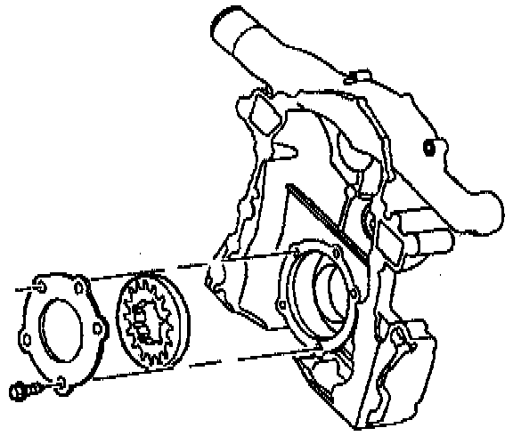
11. Oil Pump
a. Lubricate the gears with petroleum jelly.
b. Install the gears.
c. Pack the cavity with petroleum jelly.
d. Install the oil pump cover.
e. Install the oil pump cover screws. Tighten the screws to 11 Nm (98 inch lbs.).
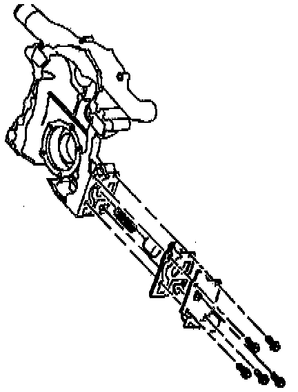
12. Oil Filter Adapter and Valve Assembly
a. Install the spring into the front cover.
b. Install the oil pressure valve into the front cover.
c. Install a new oil filter adapter gasket.
d. Install the oil filter adapter.
e. Install the oil filter adapter bolts. Tighten the bolts to 30 Nm (22 ft. lbs.).
13. Engine Front Cover
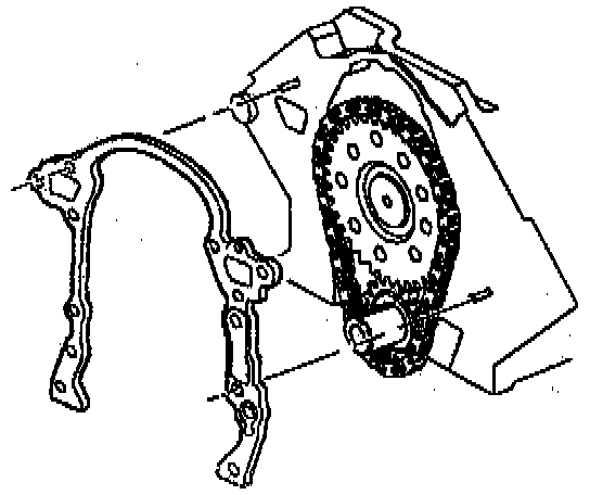
a. Install the front cover gasket.
b. Install the front cover.
c. Align the cogs on the crankshaft sprocket with the cogs on the oil pump in the front cover. Apply sealant GM P/N 12346004 or the equivalent to the front cover bolt threads.
d. Install the front cover bolts. Tighten the bolts to 15 Nm (11 ft. lbs.). Use the Torque Angle Meter in order to tighten the bolts an additional 40 degrees.
e. Install the bolts connecting oil pan to the front cover. Tighten the bolts to 14 Nm (125 inch lbs.).
f. Install the crankshaft position sensor.
g. Install the sensor shield.
14. Engine Front Cover Oil Seal
a. Coat the inside seal surface of the crankshaft balancer with lubricant GM P/N 10522497 or the equivalent.
b. Use the Seal Installer and a soft faced hammer in order to install the oil seal.
c. Remove the Seal Installer.
15. Crankshaft Balancer
a. Install the crankshaft balancer.
b. Lubricate the seal surface with engine oil.
^ Use the Flexplate Holding Tool in order to hold the flex plate.
CAUTION: This bolt is designed to permanently stretch when tightened. The correct part number fastener must be used to replace this type of fastener. Do not use a bolt that is stronger in this application. if the correct bolt is not used, the parts will not be tightened correctly. The system or the components may be damaged.
c. Install the balancer bolt. Tighten the balancer bolt to 150 Nm (111 ft. lbs.). Use the Torque Angle Meter in order to tighten the bolt an additional 76 degrees.
16. Cylinder Head
a. Use a 7/16-14 tap in order to clean threads in the block.
b. Install the head gasket. Ensure that the arrows point towards the front of the engine. The left head gasket has the letter L stamped next to the arrow.
CAUTION: This bolt is designed to permanently stretch when tightened. The correct part number fastener must be used to replace this type of fastener. Do not use a bolt that is stronger in this application. If the correct bolt is not used, the parts will not be tightened correctly. The system or the components may be damaged.
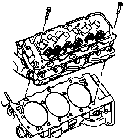
c. Install the cylinder head.
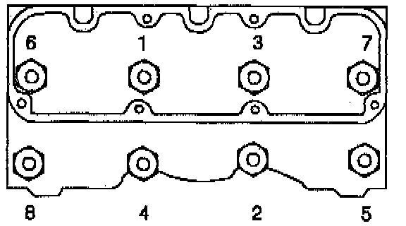
d. Install the new cylinder head bolts. Tighten the bolts to 50 Nm (37 ft. lbs.) in sequence.
^ Use the Torque Angle Meter in order to rotate each bolt 120 degrees in sequence.
^ Use the Torque Angle Meter in order to rotate the four center bolts an additional 30 degrees in sequence.
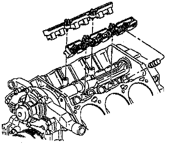
17. Valve Lifter
a. Dip the valve lifters in prelube GM P/N 12345501 or the equivalent.
b. Install the valve lifters.
c. Install the valve lifter guides.
d. Install the guide retainer.
e. Install the guide retainer bolts. Tighten the bolts to 30 Nm (22 ft. lbs.).
18. Valve Rocker Arm and Push Rod
a. Install the push rods.
b. Install the rocker arms.
CAUTION: This bolt is designed to permanently stretch when tightened. The correct part number fastener must be used to replace this type of fastener. Do not use a bolt that is stronger in this application. If the correct bolt is not used, the parts will not be tightened correctly. The system or the components may be damaged.
c. Apply thread lock compound or the equivalent to the rocker arm bolt threads.
d. Install the rocker arm bolts. Tighten the bolts to 15 Nm (11 ft. lbs.) +90 degrees using the Torque Angle Meter.
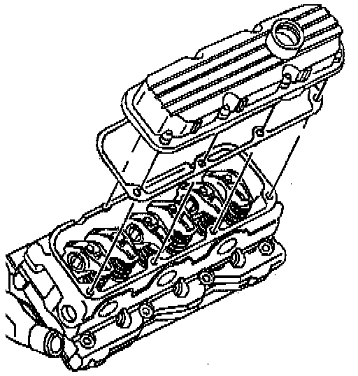
19. Valve Rocker Arm Cover (Left Side)
a. Install the rocker arm cover.
b. Clean any debris from the bolt threads.
c. Apply thread lock compound or the equivalent to the bolt threads.
d. Install the rocker arm cover bolts. Tighten the bolts to 10 Nm (89 inch lbs.).
e. Install the ICM bracket.
f. Install the engine lift bracket.
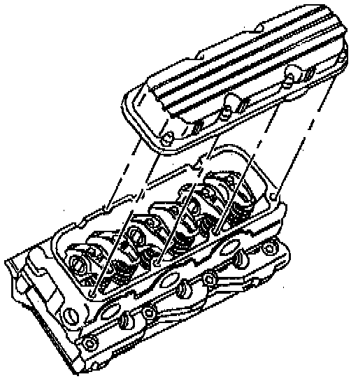
20. Valve Rocker Arm Cover (Right Side)
a. Install the rocker arm cover.
b. Apply thread lock compound or the equivalent to the bolt threads.
c. Install the rocker arm cover bolts. Tighten the bolts to 10 Nm (89 inch lbs.).
d. Install the spark plug wire.
e. Install the engine lift bracket.
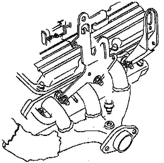
21. Exhaust Manifold (Left Side)
a. Install the exhaust manifold gasket to the cylinder head.
b. Install the manifold studs and the nuts. Tighten the studs and the nuts to 30 Nm (22 ft. lbs.).
c. Connect the spark plug wires to the spark plugs.
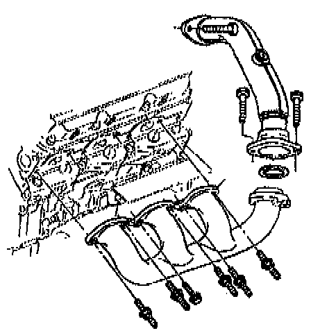
22. Exhaust Manifold (Right Side)
a. Install the exhaust manifold gasket to the cylinder head.
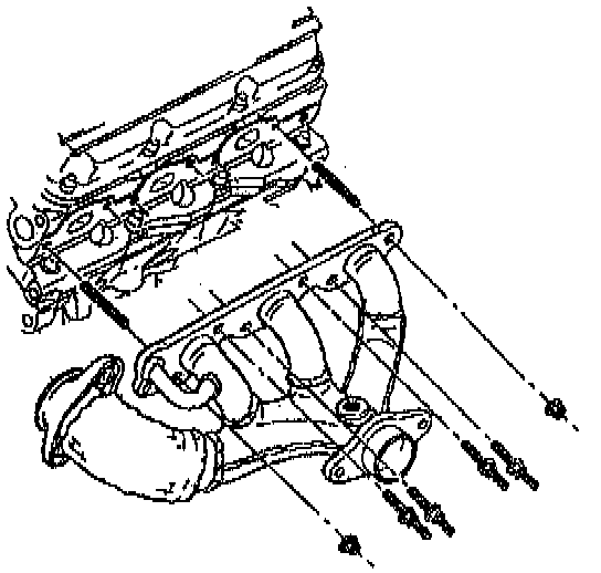
b. Install the manifold studs. Tighten the studs to 30 Nm (22 ft. lbs.).
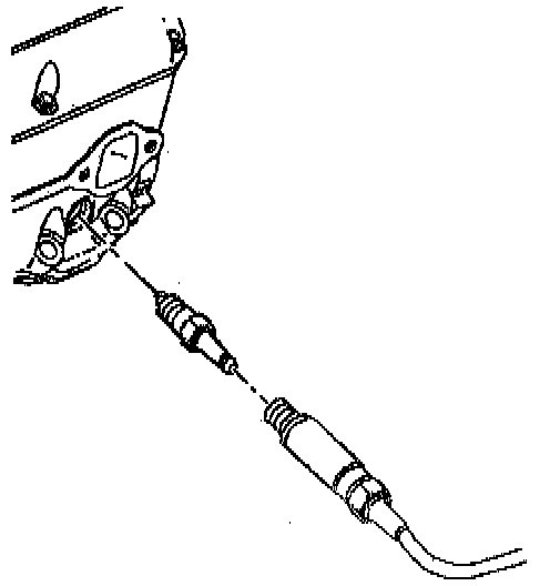
c. Install the heated oxygen sensor lead.
CAUTION: Inspect the EGR outlet pipe for leaks during installation. If leaks are present, replace the EGR adapter assembly.
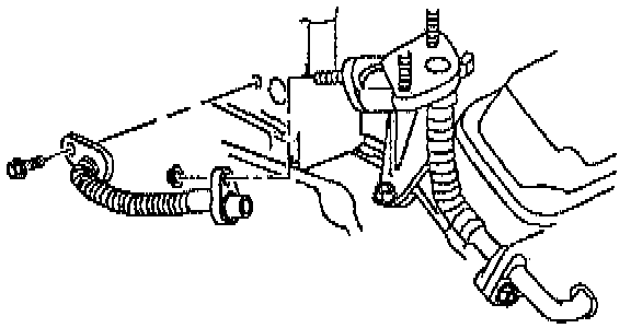
d. Install the EGR outlet pipe to the manifold.
e. Install the EGR outlet pipe to the manifold bolt. Tighten the bolt to 29 Nm (21 ft. lbs.).
23. Exhaust Crossover
a. Install the exhaust crossover.
b. Install the exhaust crossover studs to the right exhaust manifold. Tighten the studs to 20 Nm (15 ft. lbs.).
c. Install the exhaust crossover bolts to the left exhaust manifold. Tighten the bolts to 20 Nm (15 ft. lbs.).
d. Install the exhaust crossover heat shield.
e. Install the exhaust crossover heat shield nuts. Tighten the nuts to 20 Nm (15 ft. lbs.).
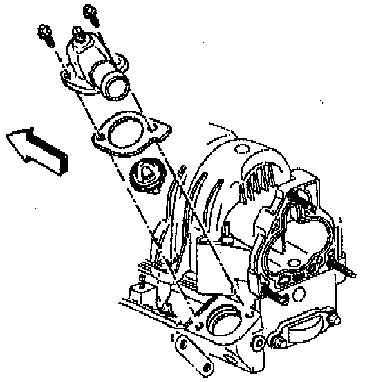
24. Intake Manifold
a. Install the intake manifold.
b. Apply thread locking compound to the bolt threads.
c. Install the intake manifold bolts. Tighten the bolts in sequence to 15 Nm (11 ft. lbs.). Make sure to install the two hidden bolts.
d. Install the engine coolant temperature sensor wiring harness to the coolant outlet stud.
e. Install the EGR outlet pipe to the intake manifold.
f. Install the upper intake manifold.
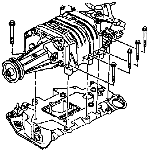
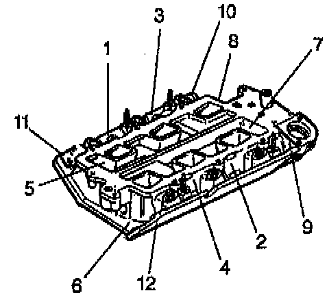
25. Supercharger
a. Install the supercharger gasket.
b. Install the supercharger.
c. Install the spacers, bolts, and stud to the supercharger in the proper locations. Tighten the stud/bolts to 23 Nm (17 ft. lbs.).
d. Install the TBI nuts. Tighten the TBI nuts to 10 Nm (89 inch lbs.).
e. Install the MAP sensor bracket bolts. Tighten the MAP sensor bracket bolts to 30 Nm (22 ft. lbs.).
f. Install the bolts to the vacuum block.
g. Install the boost solenoid bolts. Tighten the bolts to 26 Nm (19 ft. lbs.).
h. Install the regulator valve and harness bolt.
i. Install the booster bypass nut.
j. Install the fuel rail.
k. Install the fuel rail nuts. Tighten the nuts to 10 Nm (89 inch lbs.).
l. Install the vacuum line from the fuel rail.
m. Install the spark plug wire clips to the supercharger.
n. Install the ICM harness to the fuel rail.
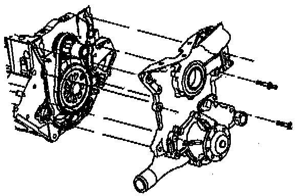
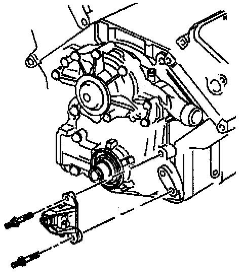
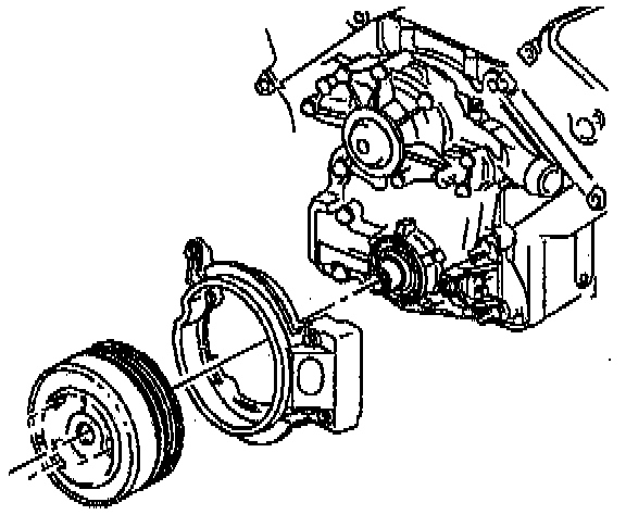
26. Water Pump
a. Install the water pump.
b. Install the water pump bolts. Tighten the bolts to 15 Nm (11 ft. lbs.). Use the Torque Angle Meter in order to tighten the bolt an additional 80 degrees.
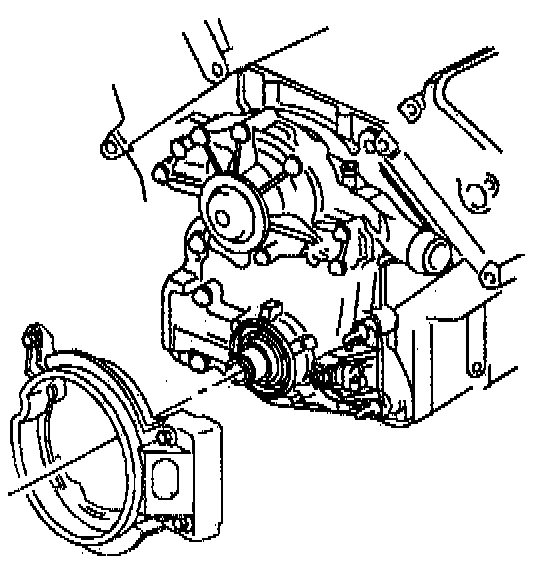
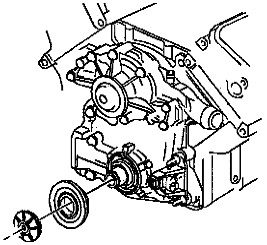
c. Install the water pump pulley.
d. Install the water pump pulley bolts. Tighten the bolts to 13 Nm (116 inch lbs.).
27. Coolant Outlet Housing and Thermostat
a. Install the thermostat.
b. Install the gasket.
c. Install the water outlet housing.
d. Install the bolts. Tighten the bolts to 27 Nm (20 ft. lbs.).

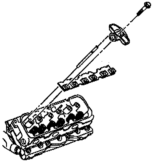
28. Oil Level Indicator and Tube
a. Install the oil level indicator.
^ Make sure that the O-ring is in place.
^ Make sure that the assembly is fully seated in the engine.
b. Install the oil level indicator nut. Tighten the nut to 10 Nm (89 inch lbs.).
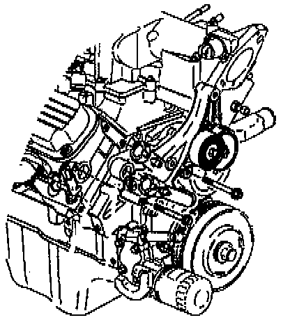
29. Drive Belt Idler Pulley Bracket
a. Install the pulley bracket.
b. Install the pulley bracket bolt. Tighten the bolt to 50 Nm (37 ft. lbs.).
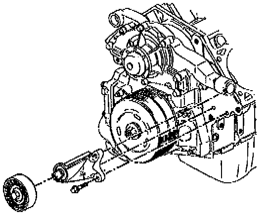
30. Accessory Drive Belt Tensioner
a. Install the drive belt tensioner.
b. Install the heater water bypass inlet pipe to the lower intake manifold and to the tensioner.
c. Install the tensioner bolts. Tighten the bolts to 50 Nm (37 ft. lbs.).
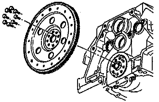
31. Engine Flex plate
a. Install the flex plate.
b. Install the new flex plate bolts. Tighten the bolts to 15 Nm (11 ft. lbs.). Use the Torque Angle Meter in order to tighten the bolts an additional 50 degrees.