Heated Oxygen Sensor (HO2S) Replacement Bank 1 Sensor 1
Heated Oxygen Sensor (HO2S) Replacement Bank 1 Sensor 1
Notice: Refer to Heated Oxygen and Oxygen Sensor Notice in Cautions and Notices
Removal Procedure
Notice: Refer to Excessive Force and Oxygen Sensor Notice in Cautions and Notices
1. Raise the vehicle. Refer to Lifting and Jacking the Vehicle in General Information.
2. Disconnect the HO2S electrical connector.
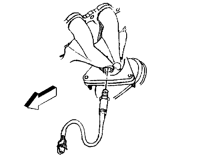
3. Carefully back out the heated oxygen sensor (H02S).
Installation Procedure
Important: A special anti-seize compound is used on the heated oxygen sensor threads. The compound consists of graphite suspended in fluid and glass beads. The graphite will burn away, but the glass beads will remain, making the sensor easier to remove. New or service sensors will already have the compound applied to the threads. If a sensor is removed from an engine and if for any reason is to be reinstalled, the threads must have anti-seize compound applied before reinstallation.
1. Coat the threads of the heated oxygen sensor with anti-seize compound P/N 5613695, or an equivalent if necessary.
Notice: Refer to Fastener Notice in Cautions and Notices.
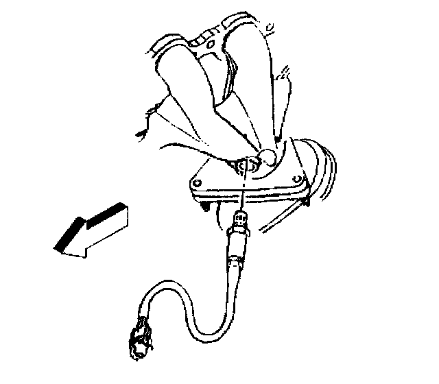
2. Install the heated oxygen sensor. Tighten the HO2S to 41 Nm (30 lb ft).
3. Connect the HO2S electrical connector.
4. Lower the vehicle.