Speed Control Kit - Installation
83saab02SUBJECT:
INSTALLING 02-06-318 SPEED CONTROL IN M84
ISSUE: 10/83-650
FILE IN S.I. MANUAL:
VOLUME: I
SECTION: 9
PAGE: 57
In order to install the Saab/Dana Speed Control Kit 02-06-318 in 1984 model cars you will need to use an adapter kit, P/N 02-06-342 and follow the changes to the instruction manual listed below. These instructions do not replace the Factory Instruction Book Number 655332. They do, however, cover all of the necessary steps to adapt to the changes in the '84 car.
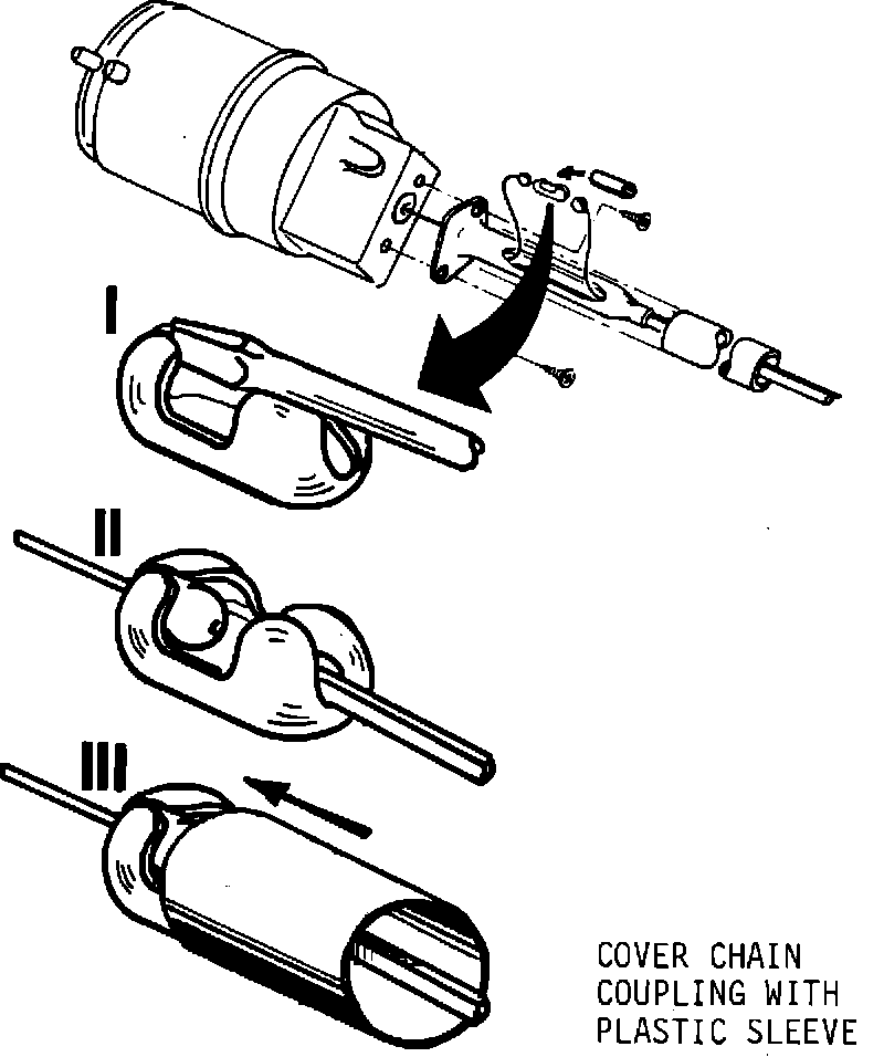
Page 4 2 Vacuum Servo
Step 5 Slide connector cover over coupling. See Illustration III below.
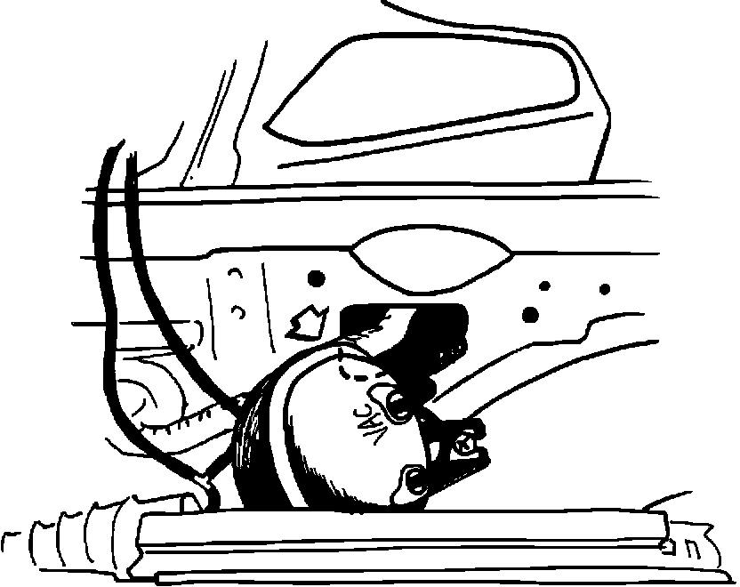
Page 5 3 Vacuum Tank With Hoses
Step 1 Fit the vacuum tank to the right hand wheel
house panel. Using the base as a template position the tank as shown in the illustration below, with the seam in the tank in line with the rear of the opening in the inner fender and the vacuum ports facing the front of the car.
Page 6 (Bottom)
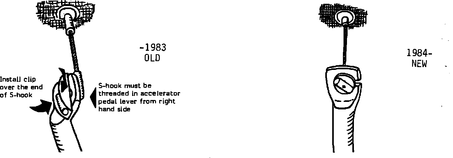
NOTE: As of the 1984 model year it is no longer necessary to install the throttle cable clip at the pedal inside the car. This is made possible by a new design for the pedal mechanism and the throttle cable. The illustration below will identify the old and the new types.
Page 10 5 Making Holes for Wires and Hose
It is no longer necessary to drill this hole. It is pre-punched at the Factory.
Page 11 6 Disengagement Switch
Automatic Transmission:
Step 1 It is no longer necessary to install the actuating bracket #234 to the brake pedal.
Step 2 Fit switch mounting bracket #235 to the empty clutch pedal bracket, and then fit switch.
Manual Gearbox:
Step 1 It is no longer necessary to install the actuating
bracket #234 to the brake pedal.
Step 2 Remove the bolt holding the clutch pedal to its
bracket.
Step 3 Fit the two switch mounting brackets to each side
of the clutch pedal. Reinstall the bolt and check for free movement of the clutch.
Step 4 It is no longer necessary to fit the activating
roller.
Step 5 Fit the two switches to their respective brackets.
Step 6 Check that the clutch pedal return spring clears
the switches. If not, bend the spring attachment on the steering tube.
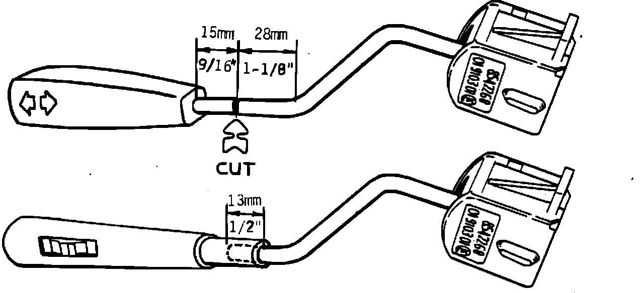
Page 13 7 Engagement Switch
Step 3 Saw off the switch arm. See illustration below.
Page 14 8 Wiring Harness
Step 1 Position and connect wiring according to the diagram on the next page.
Step 2 Fasten the wires in a suitable manner with wire ties so that they cannot be damaged by heat or moving parts.
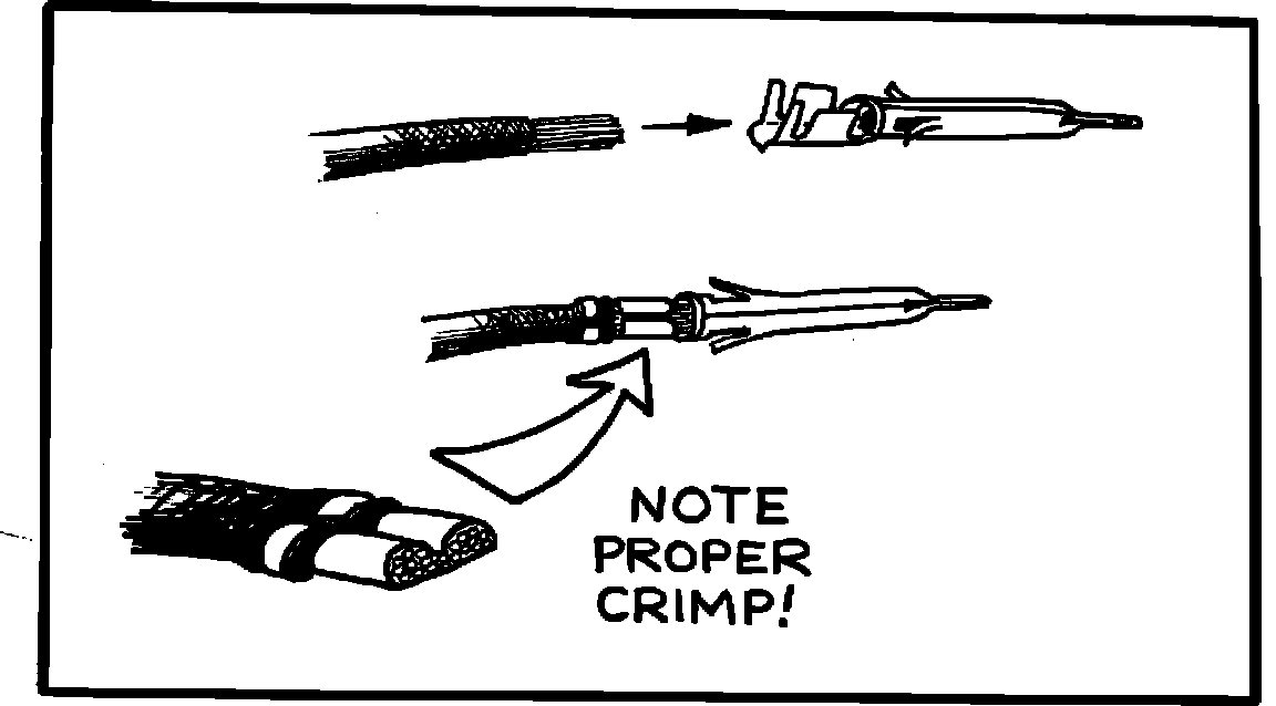
Step 3 Cut the red power wire just before the fuse. Using AMP Super Champ FT or an equivalent tool, strip 10 mm of insulation from the red wire and install the terminal P/N 85-44-272 found in the Adapter Kit. Be sure to properly crimp the connector around both the wire core and the insulation. Refer to the illustrations below.
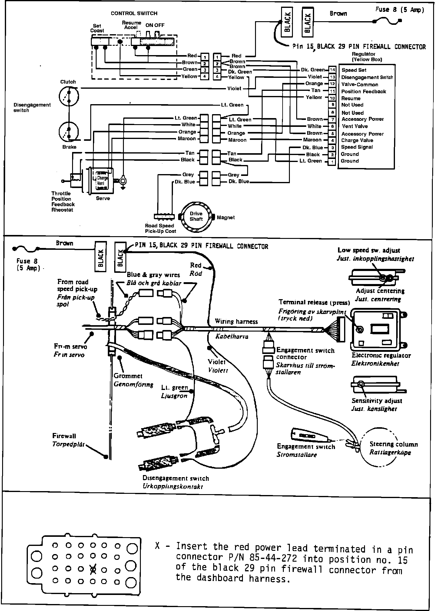
Unplug the black 29 pin dash harness connector from the left side of the firewall. Referring to the illustration on the next page, insert the red wire terminal into position 15 of the black connector. Gently pull on the wire to make sure it locks into place. Reinstall the black connector to its location on the firewall.
Remove the 10 amp fuse from position 8 of the fuse panel and install the 5 amp fuse provided in the adapter kit.
Page 14 9 Vacuum Hoses
Connect the hose between servo and the pedal switches. Route hoses in such a way that they cannot be kinked or damaged by the pedal mechanisms.
NOTE!
Remember when installing the Yellow Control Box Cruise Control that you must make a basic initial adjustment of the control box and provide the unit with a memory before attempting to make final adjustments.
Make the initial adjustments before installing the control box:
1. Set the low speed switch to the full counterclockwise position.
2. Turn the centering switch to the mid-point. (Turn fully counterclockwise and then fully clockwise to determine the stop positions to determine the mid-point.)
3. Set the sensitivity adjustment by turning fully clockwise. Back off one quarter turn counterclockwise from that point.
4. Make final adjustments during road test according to the steps outlined in the installation instructions.
During road test (and before making final adjustments) provide the unit with a memory. To do this, drive the car at 45 mph and press the "set speed" switch in. Note: This was not necessary on earlier control boxes but is mandatory on the "Yellow" box. Without this preset memory the unit WILL NOT FUNCTION!
Speed Control Tester, P/N 02-04-081 is a valuable aid in checking the wiring continuity of your installation. It is also helpful in proving the correct adjustment of the brake and clutch pedal switches.