Cylinder Head Removal

WARNING: Do not allow smoking or the use of open flames in the area where work on the fuel system is taking place. any time the fuel system is being worked on, disconnect the negative battery cable, except for those tests where battery voltage is required.
NOTE: Camshaft(s) can be removed using service tool SA9122E. Gauge bar kit SA9127E is used for pressurizing the cylinder with 690 kPa (100 psi) of air to hold the valves closed. Valve springs, caps and stem seals can be replaced without removing the cylinder head using service tool SA9124E.
1. Disconnect cable from negative terminal of battery and remove coolant bottle cap.
CAUTION: The engine's cooling system thermostat will not function correctly once it has been contacted by oil. If oil is found in the cooling system, it must be flushed and the thermostat's cartridge replaced.

2. Drain coolant from radiator and engine. (Engine drain is at right front corner of engine block under thermostat housing.)

3. Remove air cleaner cover assembly and air inlet duct. Lift the resonator upward to disengage the button from the engine service support bracket. Disconnect the cam cover air hose at cam cover.

4. Disconnect accelerator cable from throttle body and intake manifold bracket.
NOTE: The throttle body assembly, fuel rail, pressure regulator, injectors and intake manifold can be removed with cylinder head assembly from vehicle.

5. Remove the following electrical connectors:
a. Coolant temperature gauge and PCM connectors located at rear side of head.
NOTE: Use long nose pliers to remove the coolant temperature connectors.
b. Injector connectors.
c. Idle Air Control (IAC) valve.
d. Throttle Position (TP) sensor.
e. Manifold Air Pressure (MAP).
f. Remove oxygen sensor.

g. Remove spark wires.
h. Air conditioner compressor.
i. EGR Solenoid.

6. Lay harness over onto underhood junction block and battery cover.

7. Disconnect the following vacuum hoses:
a. EVAP canister purge valve.
b. PCV hose at cam cover.
c. EGR valve.
d. Fuel regulator.
e. Throttle body connector.
f. Vacuum brake booster hose at brake booster.
NOTE: The MAP sensor does not require removal.

8. Disconnect the following hoses:
a. Upper radiator hose at cylinder head outlet.
b. Deaeration hose at intake manifold.
c. Heater hose at intake manifold or front of dash.
NOTE: Use service tool SA911E (Snap-on Tool HPC10 or equivalent) to remove hose clamps.
WARNING: Catch leaking fuel in a container whenever fittings are loosened or lines are disconnected.

9. Disconnect both fuel lines:
a. Fuel pressure can be bled in to an approved container using gauge bar kit SA9127E.
b. Remove attachment bolt that clamps fuel lines to the intake manifold support brace.
c. Disconnect the fuel supply and return line to the fuel rail.
d. Remove upper intake manifold support bracket bolt.

10. Unclip the lower splash shield attachments and place a 1 inch x 1 inch x 2 inch long bock of wood between the torque strut and cradle.
NOTE: Installation of the wood block prior to upper engine torque axis mount removal allows the mount to be easily installed without lifting or jacking the powertrain.

11. Remove the three right-hand upper engine torque axis mount-to-front cover nuts and the two mount to midrail bracket nuts, allowing the powertrain to rest on the block or wood.
12. Remove the accessory drive belt and tensioner. It is not necessary to remove the water pump pulley.
CAUTION: The accessory drive belt idler pulley must be removed to allow the front cover to be removed and replaced in the vehicle.
13. Remove camshaft cover assembly.
CAUTION: Cover camshaft area whenever repairs are not being performed to prevent foreign debris from entering engine. Inspect the 12 cam cover silicone isolators for cracks. Replace the isolators if deterioration exists.

14. Remove the five power steering pump bracket attachment bolts (if equipped) and position the pump next to the right-hand front of dash panel, away from the cylinder head and intake manifold.
NOTE: It is not necessary to remove the water pump pulley.

15. Remove the three A/C compressor front bracket bolts (if equipped) attached to cylinder head and block. The rear bracket bolts can be removed from the compressor or bracket attachment to block and head. Tie the compressor assembly to the vehicle front support bar.
NOTE: The rear compressor bracket center hole is slotted for ease of compressor removal and installation. It is not necessary to discharge the A/C system.
WARNING: Make sure the vehicle is properly supported and squarely positioned prior to lifting. to help avoid personal injury when a vehicle is on a hoist, provide additional support for the vehicle on the opposite end from which components are being removed. make sure the hoist does not contact fuel or brake lines.

16. Jack or raise the vehicle on a hoist.
17. Drain engine oil.

18. Remove the right wheel and splash shield. Remove the accessory drive belt tensioner.

19. Remove the intake manifold support brace bolt attached to the intake manifold located next to the generator.

20. Remove front damper/pulley assembly. Hold damper with a strap wrench or use a 3/4 inch square x 12 inch long piece of wood wedged between the damper spoke and rear, lower side of front cover when removing the bolt. Puller jaw slots are cast into damper/pulley assembly for removal with a small three jaw puller if required.
21. Disconnect exhaust pipe from exhaust manifold. Remove the three nuts from the flange.
22. Removal of the front cover assembly:
a. Install the crankshaft gear retaining service tool SA9104E to make sure the front crankshaft timing sprocket is held firmly in place.
CAUTION: Install service tool SA9104E with flat side toward sprocket. Failure to hold the crankshaft timing sprocket in place will cause timing chain guide damage. This tool also aligns the oil pump gerotor during front cover installation. After the front cover assembly is loosened and moved approximately 25.4 mm (1 inch) from the engine, the crankshaft timing gear service tool should be removed. Spray the two dowel pin holes in the front cover with penetrating oil to prevent cover damage during removal.
b. Remove the four front oil pan bolts.

c. Use RTV cutter tool SA9123E to cut the oil pan seal away from the front cover.
d. Spray the two dowel pin holes (upper left-hand and lower right-hand side of cover) in the cover with penetrating oil to facilitate cover removal off the dowel pins.
e. Remove the front cover bolts.

f. Using a screwdriver, pry the front cover away from the cylinder block, using the pry locations shown.
NOTE: The front cover assembly can be removed from under the hood or through the wheel well.
CAUTION: Cover the front of the engine with a shop towel to prevent debris entry into the oil gallery holes and pan. Positioning crankshaft 90 degree off top dead center (TDC) to make sure pistons will not contact valves upon assembly.
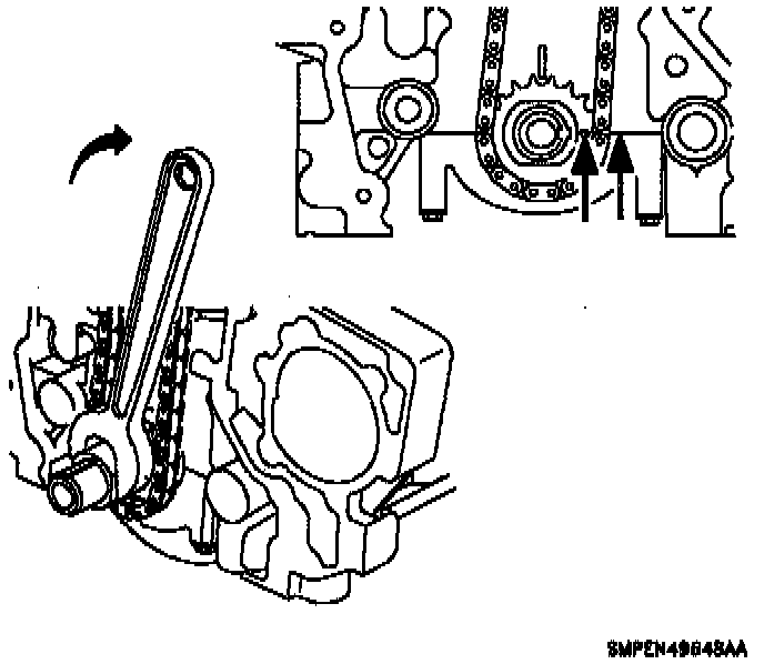
23. Rotate crankshaft clockwise (viewed from crankshaft accessory belt end) so timing mark on crankshaft sprocket and key way align with main bearing cap split line.
WARNING: The camshafts can rotate during timing chain and sprocket removal. do not place fingers or tools between the camshaft sprocket and chain during removal or assembly.

24. Remove timing chain, tensioner, guides, camshaft sprocket, and chain Use a 21 mm (7/8 inch) wrench to hold the camshaft when removing the sprocket bolt.
CAUTION: Use only a six point socket to remove the cylinder head bolts. A 12 point socket will round off the bolt head. Manufacturers of sockets have different specifications relative to diameter and the cylinder head's machine hole diameters may not allow clearance for all sockets. A six point, 3/8 inch drive, thick wall socket may be required to access bolt heads.


25. Uniformly loosen and remove the 10 head bolts in several passes, in the sequence shown:
CAUTION: Head warpage or cracking could result from removing the bolts out of order or when cylinder head is hot. Be careful not to damage the aluminum cylinder head and block gasket sealing surfaces when removing the cylinder head or during cleaning.

26. Lift the cylinder head from the dowels on the cylinder block and place the head on wooden blocks or a bench. If the cylinder head is difficult to lift off, pry with a screwdriver between the cylinder head and block bosses.