Cylinder Block Assembly

NOTE: The engine block requires the location dowel pins for the front cover, cylinder head, rear crankshaft seal carrier, and transaxle be installed with a brass driver. Dowel pins are installed until they bottom out in the cylinder block.
CAUTION: Thoroughly clean all parts to be assembled. Honed cylinders must be scrubbed with a solution of Tided powdered laundry detergent (or equivalent) and high pressure warm water prior to piston assembly. Before installing the parts, apply new engine oil to all sliding and rotating surfaces. Replace all gaskets, O-rings, and oil seals with new parts.

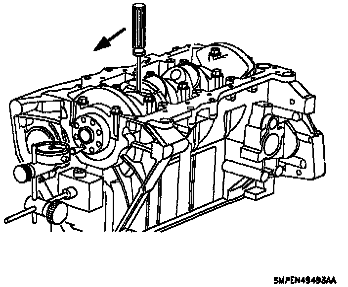
1. Install dowel pins using a brass driver.
CAUTION: Install the bearings with the oil holes in the block. The bearings with no holes must go in the main bearing caps.

2. Install main bearings:
a. Install the bearings in the cylinder block and bearing caps.
CAUTION: Inspect alignment of bearing oil hole to the block bulkhead oil feed hole. At least 50 percent of the feed hole must be open/exposed.
3. Install the thrust bearing in number three upper main bearing position of the block.
4. Place crankshaft in cylinder block and coat with engine oil.

5. Install main bearing caps.
a. Install the bearing caps in their proper locations. The arrow on the bearing cap points toward front of the cylinder block.
NOTE: Bearing caps are numbered 1-5 and have an arrow that points toward the front of the engine. No. 1 cap is at the front of the cylinder block. Use a rubber mallet and rap the crankshaft rearward, and forward in the cylinder block to make sure the thrust bearing is properly aligned.

b. Using a rubber mallet, rap the crankshaft rearward, then forward in the cylinder block to align the thrust bearing.
c. Apply a light coat of engine oil on the threads and under the heads of the cap bolts.

d. Install and uniformly tighten the 10 cap bolts in several passes in the sequence shown. Torque to 50 Nm (37 ft. lbs.).
e. Check that the crankshaft turns smoothly.
f. Check the crankshaft thrust clearance. Thrust Clearance standard is 0.050 - 0.200 mm (0.0020 - 0.0089 inch) and service limit is 0.25 mm (0.0098 inch) max. If the clearance is greater than maximum, replace the thrust bearing.
NOTE: If the crankshaft does not turn smoothly, remove the bearing caps one at a time until the tight bearing is found. Check crankshaft journal dimensions and replace bearings (upper and lower) as necessary. If a new crankshaft is installed, the PCM will be required to learn the reluctor ring notch locations of the new crankshaft.
CAUTION: Do not pull pistons down through the cylinder bores beyond their normal travel.

6. Install piston and connecting rod assemblies:
a. Cover the connecting rod bolts with a short piece of 6.36 mm (1/4 inch) inside diameter hose to protect the crankshaft from damage. Install the upper connecting rod bearings and coat with oil, if not completed previously.

b. Using the piston ring compressor service tool, push the correct piston and connecting rod assembly into each cylinder with the mark on the piston facing forward.
CAUTION: Use extreme care when installing the piston and connecting rod. The connecting rod must be properly aligned with the crank pin to prevent journal damage. It is standard practice to assemble the piston and connecting rod with bearing tang slots in the rod directed toward the exhaust manifold side.
7. Install connecting rod caps:
a. Match the marked cap with the marked connecting rod.

NOTE: The cap and rod tangs are located on the same side of the connecting rod bore.
b. Install the lower connecting rod bearing in the cap. Apply a light coat of oil on the bearing surface.

c. Install the cap with the bearing tang slots in the cap and connecting rod facing each other.
CAUTION: The machined slots in the rod and cap must be properly aligned to prevent bearing damage.
d. Apply a light coat of engine oil on the bolt threads and under the nuts of the connecting rod cap.

e. Install and alternately tighten the cap nuts in several passes. Torque to 45 Nm (33 ft. lbs.).
f. Check that the crankshaft turns smoothly.
g. Check the connecting rod side clearance.
- Side Clearance Standard is 0.165-0.435 mm (0.0065-0.1713 inch) and Service Limit is 0.470 mm (0.1850 inch) max. If clearance is less or greater than maximum, replace the connecting rod assembly. If necessary, replace the crankshaft.
CAUTION: Check the oil seal lip contact surface of the crankshaft for scratches or damage. If rust is present, remove with a Scotch-Brite pad or equivalent. Do not use emery cloth, sandpaper or other abrasive materials. Rust removal is necessary to prevent seal lip damage during installation.
- Piston Protrusion Above Deck of Block Standard is 0.300 mm (0.0118 inch) max. and Service Limit is 0.379 mm (0.0149 inch) max.
- Piston Protrusion Below Deck of Block Standard is 0.066 mm (0.0026 inch) max. and Service Limit is 0.145 mm (0.0057 inch) max.

8. Install rear oil seal carrier and seal if required:
a. Make sure surface is free of RTV and clean with a chlorinated solvent, such as carburetor spray cleaner, brake clean, or alcohol Saturn P/N 21007432 (or equivalent).
b. Install a 2.0 mm (.080 inch) diameter bead of RTV on the rear seal carrier.
NOTE: Assemble while RTV is still wet (within three minutes). Do not wait for the RTV to skin over.
9. Install the four rear crankshaft seal carrier bolts.
a. Use seal installer as a pilot to make sure the seal lip is not damaged during carrier assembly installation. Torque to 11 Nm (97 inch lbs.).
10. Install cylinder head and front cover.
NOTE: Check components for debris. Clean all parts before installation.

11. Install oil baffle plate and pickup tube with a new O-ring.
- Oil Pickup Tube To Block Torque to 15 Nm (133 inch lbs.).
- Oil Baffle Plate Torque to 55 Nm (41 ft. lbs.).
- Oil pipe bracket to baffle plate Torque to 15 Nm (133 inch lbs.).
NOTE: The oil pan is easier to install after front cover assembly installation.
12. Install the oil pan assembly and fasteners.
a. Make sure the oil pan surface is free of cured RTV and cleaned with a chlorinated solvent, such as carburetor spray cleaner, brake clean, or alcohol Saturn P/N 21007432 (or equivalent).

b. Apply a 4.0 mm (0.160 inch) bead of RTV in the oil pan groove, routing the RTV bead toward the inside of all bolt holes. Torque to 9 Nm(80 inch lbs.).
NOTE: Assemble while the RTV is still wet (within three minutes). Do not wait for the RTV to skin over.
13. Install water pump. See Cooling System.

14. Install dipstick tube with a new O-ring. Lubricate O-ring with engine oil and install into the cylinder block. Attach tube bracket to cylinder block.
15. Install the flexplate or flywheel. See Transmission and Drivetrain.
16. Install the following accessories:
a. Knock sensor.
b. Crankshaft position sensor. Lubricate O-ring with oil before installation.
c. Starter motor to block. See Starting and Charging.

CAUTION: Whenever the cylinder block has been disassembled or the oil pump is removed, fill the oil cavity under the oil filter with clean engine oil to prim the pump. The oil pump must also be packed with petroleum jelly.
d. Generator. See starting and Charging.
e. Oil filter.
f. Oil pan drain plug.
g. Oil pressure sending unit.