Dash and Cowl Panel Insulator Replacement
Dash and Cowl Panel Insulator Replacement
Removal Procedure
Important: LHD shown; RHD similar.
1. Refer to Air Conditioning and Heater Module Assembly Replacement (LHD Only) Air Conditioning and Heater Module Assembly Replacement (RHD Domestic Only) in Heating, Ventilation and Air Conditioning to gain access to the upper dash panel insulator.

Caution: Ensure that the vehicle is properly supported and squarely positioned. To help avoid personal injury when a vehicle is on a hoist, provide additional support for the vehicle on the opposite end from which the components are being removed.
2. Raise the vehicle squarely on a hoist. Refer to Lifting and Jacking the Vehicle in General Information for the procedure on positioning the vehicle on a hoist.
Notice: To prevent leaks, the bracket assembly attaching nuts must be replaced whenever they are removed.
3. Remove the accelerator bracket assembly attaching the nuts and discard.
4. Lower the vehicle.

5. Disconnect the accelerator control cable from the accelerator pedal assembly.
6. On the vehicles equipped with cruise control, disconnect the cruise control rod bracket from accelerator pedal.
7. Remove the accelerator pedal assembly.

8. Loosen the PCM retaining nut to aid in the removal of the insulator.

Important: The following steps modify the original insulator to mate to the replacement insulator. Care must be taken to preserve the top portion of the original insulator because it may remain in the vehicle. If the windshield is NOT in the vehicle, skip steps 9 and 10.
9. Using a tape measure, mark 2.5 mm (1 in) from plenum flange area to the approximate center of the plenum front. This is a vertical measurement.
10. Using a utility knife, cut horizontally across the top of the insulator at the plenum front marked in step 9.

Important: Once removed, the popcorn fasteners cannot be reused.
11. If the vehicle's windshield is out of the vehicle, remove the popcorn fasteners.
* In 2001 vehicles, there is only one popcorn fastener.
* For all 2000 vehicles, there are two popcorn fasteners.

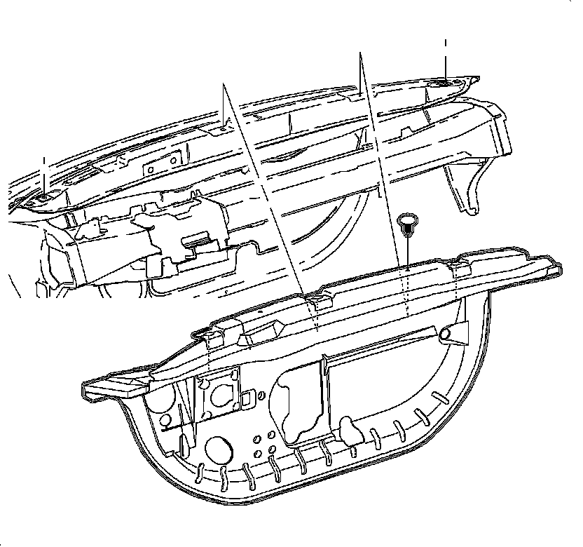
12. At the I/P wiring harness location, the insulator has a "D-shape" partial cut out (1). Find the 4 o'clock position and cut diagonally to the left side of the steering wheel brace in order to free the insulator.
13. Locate the I/P wiring harness at the left top of the insulator. On manual transmission vehicles, the clutch pushrod will be directly below the I/P wiring harness.
14. Locate the 2 o'clock position on the insulator at the steering intermediate shaft hole. Cut the insulator diagonally from the intermediate shaft hole to the right side of the steering column brace in order to free the insulator.
Important: Removal of the insulator may require maneuvering the insulator around the nonremovable parts.
15. Remove the insulator from the vehicle.
Installation Procedure
Important: LHD shown; RHD similar.
1. Place the new insulator on a clean bench. Position it so the top is farthest away from you and the bottom is the closest. The black rubber side should be facing up.
2. Locate the "D-shape" partial cutout at the left of the insulator. Find the 4 o'clock position and cut diagonally between the outside of the "D" and the vertical cut for the left side of the steering wheel brace.
3. Locate the 10 cm x 6.5 cm (3 15/16 in x 2 9/16 in) oblong hole at the bottom left of the insulator. Cut diagonally at the 2 o'clock position to the vertical cut for the right side of the steering wheel brace.
4. While on the bench, using a tape measure, mark 2.5 cm (1 in) from plenum flange area of the insulator to the approximate center of the plenum front. This is a vertical measurement.
5. Using a utility knife, cut horizontally across the top of the insulator at the plenum front marked in the previous step.
6. Place the insulator in position entering the passenger's side of the car.
7. Align the insulator with the front of the lower cowl, starting at the passenger's side and working toward the center. Once the insulator is lined up with the contour of the lower cowl on the passenger's side and center of the vehicle, begin to position the drivers side.
8. Route the top of the insulator around the various wiring harnesses and components of the driver's side.
Important: If the windshield is IN the vehicle, skip steps 9-11.
9. On vehicles with the windshield removed, position the insulator to the plenum.
10. Attach the insulator to the plenum with new popcorn fasteners.
1. For 2001 vehicles, there is only one popcorn fastener.
2. For all 2000 vehicles, there are two popcorn fasteners.

11. Once the new insulator is in place, mate the remaining portion of the original insulator with the new one. Trim as necessary with a utility knife.
Important: If the windshield is OUT of the vehicle, skip Steps 12-14.
12. Obtain three dash and cowl deadeners (1). Cut the deadeners to 26 cm x 4.5 cm (10 1/4 in x 1 3/4 in).
Important: Be certain not to place any of the deadener material onto the portion of the insulator that covers the wiper module assembly.
13. Attach the new insulator to the old insulator, using three dash and cowl deadeners across the front.
Notice: Torque is critical to preserve the integrity of the plastic insulator on the PCM case. Damage to the PCM can result from over torque of the nut.
14. Install the PCM in the proper position and tighten the nut.
Tighten the PCM Attachment Nut to 10 Nm (89 in lb).
15. Install the accelerator bracket assembly onto the dash panel.
16. Install the accelerator control cable to the accelerator pedal.
Important: Cruise control must be adjusted upon installation of the cruise control module and cable.
17. On vehicles equipped with cruise control, attach the cruise control cable to the acceleration pedal assembly. Refer to Cruise Control Module Replacement in Cruise Control.
Caution: Ensure that the vehicle is properly supported and squarely positioned. To help avoid personal injury when a vehicle is on a hoist, provide additional support for the vehicle on the opposite end from which the components are being removed.
18. Raise the vehicle squarely on a hoist. Refer to Lifting and Jacking the Vehicle in General Information for the procedure on positioning the vehicle on a hoist.
19. Install the new accelerator bracket assembly attaching nuts.
Tighten the accelerator pedal attachment nut to 12 Nm (9 lb ft).
20. Lower vehicle.
21. Check accelerator control assembly.
22. Refer to Air Conditioning and Heater Module Assembly Replacement (LHD Only) Air Conditioning and Heater Module Assembly Replacement (RHD Domestic Only) in Heating, Ventilation and Air Conditioning to complete installation of the upper dash panel insulator.