Cylinder Head Cleaning and Inspection

- Tools Required
- SA9177NE Straight Edge
- SA91101NE Feeler Gauge Set
- J-43481 Valve Guide Go-No Go Gauge
- SA91102NE Gauge Ball Set
- J-43225 Valve Guide Remover/Installer
- SA9126E-10 Valve Guide Reamer
- SA9179NE Dial Indicator

1. Clean top of pistons and top of block:
a. Turn the crankshaft and bring each piston to Top Dead Center (TDC). Using a gasket scrapers remove all the carbon from the piston top.
IMPORTANT: Cover front of the engine with a shop towel to prevent debris from entering the oil gallery holes and pan.
CAUTION: PROTECT YOUR EYES WHEN USING HIGH PRESSURE AIR.
b. Remove all the gasket material from the top of the block using a plastic or wood scraper.
c. Blow carbon and oil from the bolt holes.
NOTICE: Be careful not to scratch or score the cylinder block and head aluminum surfaces when cleaning.

2. Remove gasket material from cylinder head:
a. Using a plastic or wood gasket scraper, remove all the gasket material from the manifold and head surface.
NOTICE:
- Intake and exhaust manifold stud threads can be damaged during removal and must be replaced when a new machined cylinder head casting is installed.
- Be careful not to scratch the head gasket contact surface when cleaning cylinder head.

3. Using a wire brush, remove all the carbon from the combustion chambers.

4. Using a valve guide bushing brush and solvent, clean all the valve guide bushings.
5. Using a soft brush and solvent, thoroughly clean the cylinder head:
a. Intake and exhaust ports.
b. Intake and exhaust valve seats and guides.
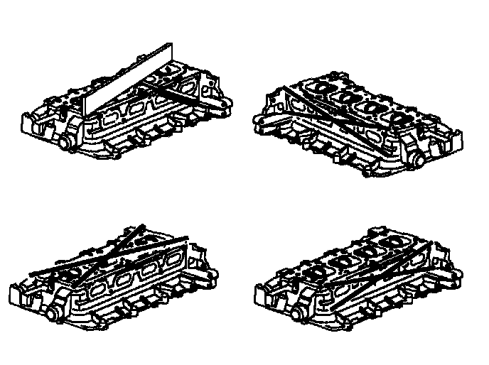
6. Inspect cylinder head for flatness. Using a precision straight edge SA9177NE (or equivalent) and feeler gauge SA9llOlNE (or equivalent), measure the surfaces contacting the cylinder block and manifolds for warpage. If warpage is greater than maximum, replace the cylinder head.
Maximum Warpage Specifications:
Cylinder Block Side:
Transverse:
Standard: 0.03 mm (0.0012 inch)
Service Limit: 0.05 mm (0.002 inch) max.
Longitudinal:
Standard: 0.07 mm (0.0028 inch)
Service Limit: 0.10 mm (0.004 inch) max.
Intake Manifold Side: Longitudinal:
Standard: 0.10 mm (0.004 inch)
Service Limit: 0.15 mm (0.006 inch) max.
Exhaust Manifold Side:
Longitudinal:
Standard: 0.10 mm (0.004 inch)
Service Limit: 0.15 mm (0.006 inch) max.
EGR Flange:
Standard: 0.10 mm (0.004 inch) max.
Service Limit: 0.15 mm (0.006 inch) max.

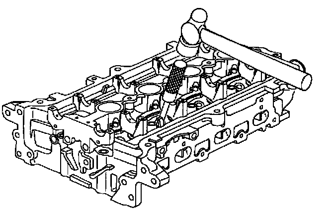
7. Inspect cylinder head for cracks. Using a dye penetrate, check the combustion chamber intake and exhaust ports, head surface, and the top of the head (around all bolt holes) for cracks. If cracked, replace the cylinder head.

8. Clean the valves:
a. Using a gasket scraper, or wire brush, remove any carbon from the valve head.

9. Inspect valve stems and guides for wear, scratches, and burrs.
IMPORTANT: A small scratch, score or scuff on the valve stem will damage and wear out the valve stem seal.

a. The valve guide I.D. can be inspected for proper size by using go/ no-go pin gauge J-43481. The valve guide I.D. must free of carbon deposits. A wire brush and solvents can be used to remove carbon deposits.
Refer to "Valve Guide Identification Measurement" in the "Engine Diagnostic" for proper G0/No-Go gauge usage.
To calculate oil clearance between the valve stem and valve guide, measure the guide bushing at three locations using a ball gauge SA91102NE (or equivalent).
Guide Bushing Inside Diameter
Standard: 6.000 - 6.020 mm (0.2364 - 0.2372 inch)
Service Limit: 6.060 mm (0.239 inch) max.

b. Using a micrometer, measure the diameter of the valve stem.
Valve Stem Diameter:
Intake:
Standard: 5.958 - 5.997 mm (0.2347 - 0.2372 inch)
Service Limit: 5.945 mm (0.2342 inch) min.
Exhaust:
Oil Clearance:
Intake:
Standard: 5.944 - 5.963 mm (0.2342 - 0.2349 inch) min.
Service Limit: 5.930 mm (0.2336 inch) min.
c. Subtract the valve stem diameter measurement from the valve guide bushing inside diameter measurement. If the clearance is greater than maximum, replace the valve and guide bushing.
Oil Clearance:
Intake:
Standard: 0.025 - 0.064 mm (0.001 - 0.0025 inch)
Service Limit: 0.115 mm (0.0044 inch) max.
Exhaust:
Standard: 0.037 - 0.082 mm (0.0015 - 0.0032 inch)
Service Limit: 0.131 mm (0.005 inch) max.
10. If necessary, replace valve guide bushings:
a. Using the driver J-43225 and a hammer, drive out the valve guide bushing.

b. Using a ball hole gauge or SA91102NE (or equivalent), measure the bushing bore diameter in the cylinder head. If the bushing bore diameter of the cylinder head is more than 11.368 mm (0.4475 inch), use the large reamer SA9126E-5 and ream the bore to the following dimensions to install an oversized bushing (11.587 - 11.613 mm [0.456 - 0.457 inch]). If the bushing bore diameter of the cylinder head exceeds 11.613 mm (0.457 inch), replace the cylinder head.
Cylinder Head Valve Guide Bore (Cold): Standard: 11.337 - 11.363 mm (0.446 - 0.447 inch)
Service Limit: 11.368 mm (0.4475 inch) max.
Oversize Bore: 11.587 - 11.613 mm (0.456 - 0.457 inch)


c. Using drivers J-43225-3 and a hammer, drive in a new valve guide bushing.
Guide Height above Cylinder Head Valve: Spring Seat: 8.30 - 8.55 mm (0.3270 - 0.3369 inch)
IMPORTANT:
- Do not oil or use any thread locking materials when installing valve guides.
- Do not use the 1991 - 1998 model year reamer. This reamer is 7 mm in diameter. The 2000 DOHC valve guide is 6 mm in diameter. Use the correct reamer for 2000 DOHC engine (SA9126E-10).

d. Using a sharp reamer SA9126E-10, ream the valve guide bushing to obtain the specified clearance between the valve guide bushing and the new valve stem.
IMPORTANT:
- Oil the reamer with SAE SW30 SO engine or cutting oil. Slowly drive the small reamer through the valve guide bore with a 1/2 HP drill motor set at 500 rpm. Check the valve guide bore to valve stem clearance.
- Make sure the reamer flutes are clean prior to reaming each guide.
Clearance:
Intake:
Standard: 0.025 - 0.064 mm (0.001 - 0.0025 inch)
Service Limit: 0.115 mm (0.0044 inch) max.
Exhaust:
Standard: 0.037 - 0.082 mm (0.0015 - 0.0032 inch)
Service Limit: 0.131 mm (0.005 inch) max.

11. Inspect and grind valves:
a. Grind the valve only enough to remove pits and carbon.
IMPORTANT: If the valve head is cupped, it must be replaced.

b. Check that the valve is ground to the correct valve face angle.
Valve Face Angle: Intake and Exhaust
Standard: 44.5 - 45.0 degrees

c. Check the valve head margin thickness. If the valve head margin thickness is less than minimum, replace the valve.
Margin Thickness:
Intake:
Service Limit: 0.75 mm (0.0295 inch) min.
Exhaust:
Service Limit: 0.75 mm (0.0295 inch) min.

d. Check the valve overall length. If the valve overall length is less than minimum, replace the valve.
Minimum Overall Length:
Intake:
Standard: 96.28 - 96.74 mm ( 3.7934 - 3.8116 inch)
Service Limit: 96.20 - 96.74 mm (3.787 - 3.812 inch)
Exhaust:
Standard: 95.58 - 96.04 mm (3.7659 - 3.7840 inch)
Service Limit: 95.50 - 96.04 mm (3.760 - 3.784 inch)
NOTICE: Do not grind off more than the minimum overall length.

e. Check the surface of the valve stem tip for damage. If the valve stem tip is damaged, grind the valve stem tip with a grinder until flat. Replace the valve if necessary.

12. Inspect and clean valve seats.
IMPORTANT: Valve seats are released for service and can be replaced. Damaged seats are usually replaced by a machine shop.
Cylinder Head Dimensions:
Intake Valve Seat Bore:
Standard: 33.399 - 33.423 mm (1.315 - 1.316 inch)
Exhaust Valve Seat Bore:
Standard: 28.399 - 28.423 mm (1.118 - 1.119 inch)
Valve Seat Outside Diameter: Intake:
Standard: 33.49 - 33.51 mm (0.318 - 0.319 inch)
Exhaust:
Standard: 28.49 - 28.51 mm (1.121 - 1.122 inch)

a. Using a 44.5 - 45 degree carbide cutter or stone, resurface the valve seats. Remove only enough metal to clean the seats. Check the valve seat width:
Valve Seat Width: Intake:
Standard: 0.79 - 1.23 mm (0.031 - 0.048 inch)
Service Limit: 1.66 mm (0.0653 inch) max.
Exhaust:
Standard: 1.05 - 1.49 mm (0.041 - 0.058 inch)
Service Limit: 1.92 mm (0.0756 inch) max.

b. Check the valve seating position. Apply a thin coat of Prussian blue (or white lead) to the valve face. Install the valve. While applying light pressure to the valve, rotate the valve against the seat.
c. Check the valve face and seat for the following:
- If blue appears 360 degrees around the face, the valve is concentric. If not, replace the valve.
- If blue appears 360 degrees around the valve seat, the guide and seat are concentric. If not, resurface the seat.
- Check that the seat contact is on the middle of the valve face. If not, correct the valve seat as follows:

- If the seating is too high on the valve face, use 30 degrees and 45 degree cutters or stones to correct the seat width.

- If the seating is too low on the valve face, use 60 degrees and 45 degree cutters or stones to correct the seat.

d. Hand-lap the valve and valve seat with an abrasive compound.
e. Clean the valve and valve seat after lapping using solvent.

f. Install the valve without seal and measure the tip height with calipers.
Maximum Height Dimension:
Standard: 39.31 - 39.98 mm (1.548 - 1.567 inch)
Service Limit: 39.31 mm (1.548 inch) min.
40.28 mm (1.586 inch) max.

13. Inspect valve springs:
a. Using a ruler, measure the height of the valve spring at four locations. If the valve spring is bent, replace it.
Maximum Squareness:
Standard: 2.0 mm (0.080 inch) max.
Service Limit: 2.5 mm (0.100 inch) max.

b. Using calipers or service tool SA9179NE (or equivalent), measure the free length of the valve spring. If the free length is not within specification, replace the valve spring.
Free Length: (Reference Only)
Standard: 40.10 mm (1.58 inch) min.

c. Using a spring tester SA9183NE (or equivalent), fully collapse the spring three times, then measure the tension of the valve spring at the specified installed length. If the installed tension is not as specified, replace the valve spring.
Tension at 21.50 mm (0.847 inch):
Standard: 440 - 486 N (99 - 109 lbs.)
Service Limit: 420 N (94 lbs.) min.
Tension at 31.00 mm (1.221 inch):
Standard: 186 - 214 N (42 - 48 lbs.)
Service Limit: 180 N (40 lbs.) min.

14. Check the lash adjuster diameter and cylinder head bore for wear.
Lifter Diameter
Standard: 11.986 - 12.000 mm (0.4722 - 0.4728 inch)
Service Limit: 11.980 mm (0.4720 inch) min.
Cylinder Head Bore Diameter:
Standard: 12.008 - 12.030 mm (0.4371 - 0.4740 inch)
Service Limit: 12.040 mm (0.4744 inch) max.
Oil Clearance:
Standard: 0.008 - 0.044 mm (0.0003 - 0.0017 inch)
Service Limit: 0.060 mm (0.0024 inch) max.
NOTICE: Lifters must be installed in the same bores. Lifters are very difficult to repair and must be replaced as an assembly.

15. Inspect and clean lifters (externally):

16. Inspect exhaust manifold. Using a precision straight edge and feeler gauge, measure for warpage. If warpage is greater than maximum, replace the manifold.
Warpage:
Exhaust Manifold-to-Cylinder Head:
Standard: 0.25 mm (0.010 inch) max.
Service Limit: 0.35 mm (0.014 inch) max.
Exhaust Manifold-to-Front Exhaust Pipe Flange:
Standard: 0.4 mm (0.016 inch) max.
Service Limit: 0.4 mm (0.016 inch) max.