12. Cylinder Block Assembly
- Tools Required
- J-41742 Connecting Rod Guide Pins
- J-44057 Tie Plate Socket
- SA9142E Piston Ring Compressor

NOTICE: Engine block require the location dowel pins for the front cover, cylinder head, rear crankshaft seal carrier, and transaxle be installed with a brass driver. Dowel pins are installed until they bottom out in the cylinder block.
IMPORTANT: Thoroughly clean all parts to be assembled. Honed cylinders must be scrubbed with a solution of Tide powdered laundry detergent (or equivalent) and high pressure warm water prior to piston assembly. Before installing the parts, apply new engine oil to all sliding and rotating surfaces. Replace all gaskets, O-rings, and oil seals with new parts.

1. Install dowel pins using a brass driver.
NOTICE: Install the bearings with the oil holes in the block. The bearings with no holes must go in the main bearing caps.

2. Install main bearings:
a. Install the bearings in the cylinder block and bearing caps.
NOTICE: Inspect alignment of bearing oil hole to the block bulkhead oil feed hole. At least 50 percent of the feed hole must be open/exposed.
3. Install the thrust bearing in number three upper main bearing position of the block.

4. Place crankshaft in cylinder block and coat with engine oil.
5. Install main bearing caps.
a. Install the bearing caps in their proper locations. The arrow on the bearing cap points toward front of the cylinder block.
IMPORTANT: Bearing caps are numbered 1 - 5 and have an arrow that points toward the front of the engine. No. 1 cap is at the front of the cylinder block.

IMPORTANT: Use a rubber mallet and rap the crankshaft rearward, and forward in the cylinder block to make sure the thrust bearing is properly aligned.
b. Using a rubber mallet, rap the crankshaft rearward, then forward in the cylinder block to align the thrust bearing.
c. Apply a light coat of engine oil on the threads and under the heads of the cap bolts.

d. Install and uniformly tighten the 10 cap bolts in several passes, in the sequence shown.
Torque: 50 Nm (37 ft. lbs.)
e. Check that the crankshaft turns smoothly.
f. Check the crankshaft thrust clearance.
Thrust Clearance:
Standard: 0.050 - 0.200 mm (0.0020 - 0.0089 inch)
Service Limit: 0.25 mm (0.0098 inch) max.
If the clearance is greater than maximum, replace the thrust bearing.
IMPORTANT:
- If the crankshaft does not turn smoothly, remove the bearing caps one at a time until the tight bearing is found. Check crankshaft journal dimensions and replace bearings (upper and lower) as necessary.
- If a new crankshaft is installed, the Powertrain Control Module (PCM) will be required to learn the reluctor ring notch locations of the new crankshaft.
NOTICE: Do not pull pistons down through the cylinder bores beyond their normal travel.

6. Install piston and connecting rod assemblies:
a. Install connecting rod guides J41742 to connecting rod bolt holes. The guides are required to prevent damage to the crankshaft rod journals. Install the upper connecting rod bearings and coat with oil, if not completed previously.
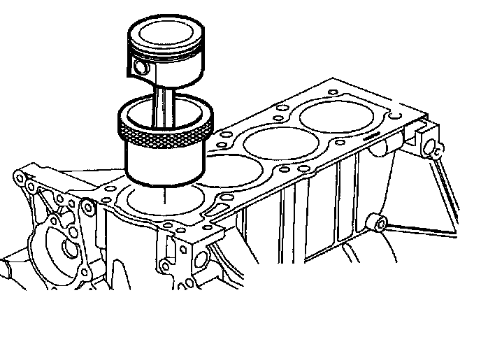
b. Using the piston ring compressor service tool SA9142E, push the correct piston and connecting rod assembly into each cylinder with the two eyebrow cuts on the piston facing toward the intake manifold side of engine block.

c. Verify proper piston pin orientations by looking at underside of pistons. Ensure piston pin boss with the rectangular-shape casting feature is pointing toward back of engine.
IMPORTANT: The powdered metal connecting rod and cap are machined for the proper clearances. The connecting rod and cap must be used as an assembly with no repair or modifications to either mating surface.

Do not attempt to repair the connecting rod or the cap mating surfaces. If service is required, the connecting rod and cap must be replaced as an assembly.
IMPORTANT: Use extreme care when installing the piston and connecting rod. The connecting rod must be properly aligned with the crank pin to prevent journal damage. It is standard practice to assemble the piston and connecting rod with bearing tang slots in the rod directed toward the exhaust manifold side.
7. Install connecting rod caps:

IMPORTANT: Connecting rods and rod caps which are assembled properly will have matching serial numbers located as illustrated.
The large end of the connecting rod will have machined surfaces that appear as illustrated when properly assembled.
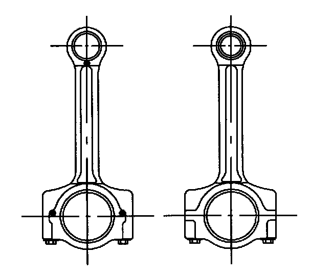
a. Match the serial number of the cap with the serial number of the connecting rod.
IMPORTANT: The cap and rod tangs are located on the same side of the connecting rod bore.
b. Install the lower connecting rod bearing in the cap. Apply a light coat of oil on the bearing surface.

c. Install the cap with the bearing tang slots in the cap and connecting rod facing each other.
IMPORTANT:
- The machined slots in the rod and cap must be properly aligned to prevent bearing damage.
- The connecting rod bolts are torque-to-yield fasteners. The number of times the bolts can be used is limited. New bolts, which have never been tightened, must be used when the connecting rod and rod cap are final assembled in the engine.

d. Install and alternately tighten the cap bolts in several passes.
Torque: 25 Nm (19 ft. lbs.) + 75 degrees
e. Check that the crankshaft turns smoothly.
f. Check the connecting rod side clearance.
Side Clearance:
Standard: 0.165 - 0.435 mm (0.0065 - 0.1713 inch)
Service Limit: 0.470 mm (0.1850 inch) max.
If clearance is less or greater than maximum, replace the connecting rod assembly. If necessary, replace the crankshaft.
NOTICE: Check the oil seal lip contact surface of the crankshaft for scratches or damage. If rust is present, remove with a Scotch-Brite pad or equivalent. Do not use emery cloth, sandpaper or other abrasive materials. Rust removal is necessary to prevent seal lip damage during installation.
Piston Protrusion Above Deck of Block
Standard: 0.300 mm (0.0118 inch) max.
Service Limit: 0.379 mm (0.0149 inch) max.
Piston Protrusion Below Deck of Block
Standard: 0.066 mm (0.0026 inch) max.
Service Limit: 0.145 mm (0.0057 inch) max.

8. Install rear oil seal carrier and seal if required:
a. Make sure surface is free of RTV and clean with a chlorinated solvent, such as carburetor spray cleaner, brake clean, or alcohol Saturn P/N 21007432 (or equivalent).
b. Install a 2.0 mm (0.080 inch) diameter bead of RTV on the rear seal carrier.
IMPORTANT: Assemble while RTV is still wet (within three minutes). Do not wait for the RTV to skin over.
9. Install the four rear crankshaft seal carrier bolts.
a. Use seal installer SA9121E as a pilot to make sure the seal lip is not damaged during carrier assembly installation.
Torque: 11 Nm (97 inch lbs.)

10. Refer to cylinder head and front cover installation.
IMPORTANT: Check components for debris. Clean all parts before installation.
11. Install crankshaft bearing tie plate (DOHC [LL0]) and oil pickup tube with a new O-ring.
IMPORTANT:
- Prior to assembly to the engine, tie-plate inserts must be rotated counter clockwise to recess the inserts within the tie plate. Failure to follow this procedure could result in tie-plate fracture and could cause engine damage.
- The tie-plate is assembled to the engine with the large rectangular opening located at rear of engine.
a. Install crankshaft bearing tie-plate over main bearing cap studs.
b. Install six crankshaft bearing tie-plate fasteners to the oil pan rail on the engine block.
Torque: 55 Nm (41 ft. lbs.)

c. Install tie-plate inserts. Rotate inserts clockwise to bring inserts into contact with bearing cap studs. Use tie plate socket J-44057.
Torque: 3.5 Nm (31 inch lbs.)
IMPORTANT: Replace tie-plate washers with new washers when assembling tie-plate to engine.
d. Install washers over bearing cap studs onto inserts.
e. Install ten nuts to bearing cap studs.
Torque: 25 Nm (18 ft. lbs.)
f. Install oil pickup tube.
Oil pickup tub to block:
Torque: 15 Nm (133 inch lbs.)
Oil pickup tub to tie-plate:
Torque: 15 Nm (133 inch lbs.)
IMPORTANT: The oil pan is easier to install after front cover assembly installation.

12. Install the oil pan assembly and fasteners.
a. Make sure the oil pan surface is free of cured RTV and cleaned with a chlorinated solvent, such as carburetor spray cleaner, brake clean, or alcohol Saturn P/N 21007432 (or equivalent).
b. Apply a 4.0 mm (0.160 inch) bead of RTV in the oil pan groove, routing the RTV bead toward the inside of all bolt holes.
Torque: 9 Nm (80 inch lbs.)
IMPORTANT: Assemble while the RTV is still wet (within three minutes). Do not wait for the RTV to skin over.

13. Install water pump:
Install a new gasket. Use a small amount of RTV in three or four spots around the outer bolt holes to hold the gasket in place. Refer to the Cooling System for water pump installation.
Water Pump:
Torque: 30 Nm (22 ft. lbs.)
Water Pump Pulley:
Torque: 25 Nm (19 ft. lbs.)
14. Install dipstick tube with a new O-ring. Lubricate O-ring with engine oil and install into the cylinder block. Attach tube bracket to cylinder block.
Torque: 30 Nm (22 ft. lbs.)

15. Install the flexplate or flywheel. The flexplate and flywheel can be installed at any bolt hole location. The flexplate or flywheel can be held with a flywheel turning tool when torquing the bolts.
a. Flexplate to crankshaft
Torque: 60 Nm (44 ft. lbs.)
b. Flywheel to crankshaft
Torque: 80 Nm (59 ft. lbs.)
16. Install the following accessories:
a. Knock sensor
Torque: 15 Nm (133 inch lbs.)
b. Crankshaft position sensor. Lubricate O-ring with oil before installation.
Torque: 9 Nm (80 inch lbs.)
c. Starter motor to block
Torque: 37 Nm (27 ft. lbs.)

IMPORTANT: Whenever the cylinder block has been disassembled or the oil pump is removed, fill the oil cavity under the oil filter with clean engine oil to prime the pump. The oil pump must also be packed with petroleum jelly.
d. Generator
Torque: 32 Nm (24 ft. lbs.)
e. Oil filter
Torque: Gasket contact and 3/4 to 1 turn
f. Oil pan drain plug
Torque: 37 Nm (27 ft. lbs.)
g. Oil pressure sending unit
Torque: 45 Nm (33 ft. lbs.)