18. RTV Sealant and Components
- Tools Required
- SA9123E Gasket Seal Cutter
REMOVAL

IMPORTANT: The following removal and installation procedures are general. Refer to the specific component for detailed information, including torque specifications.
Room Temperature Vulcanize (RTV) sealant is used in six locations on the engine as a gasket or sealant:
- Oil pan
- Front cover
Rear crankshaft seal carrier
Front cover, cylinder head, cam cover T-joints
- Vibration damper/pulley washer
IMPORTANT: Disassembly of components sealed with RTV requires that specific procedures be followed. d. RTV cutter tool SA9123E is required for oil pan removal. The engine's front cover and rear seal carrier have pry tangs to break the component loose from the cylinder block. The cam cover gasket is a procured gasket.
Oil Pan-In-Chassis

1. Remove the front exhaust pipe.
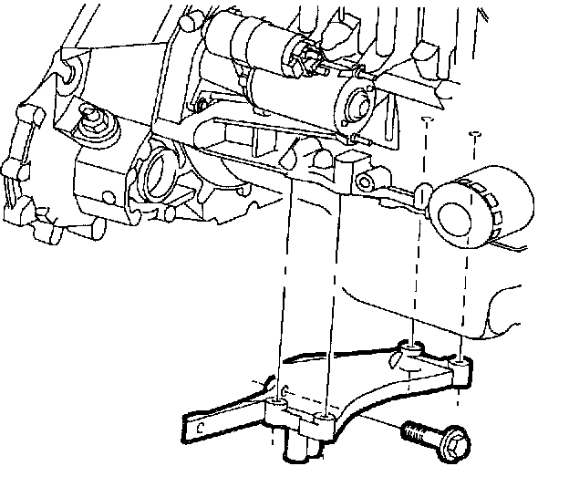
2. Remove the engine stiffening bracket and flywheel cover.

3. Remove the right-hand side tire, splash shield and vibration damper.
4. Loosen the four front motor mount bolts. Back out the bolts approximately 12 mm (1/2 inch).
5. Drain oil.
6. Remove all the oil pan bolts.
IMPORTANT: An 8 mm flex socket can be used to access the rear oil pan bolt heads next to the flywheel on vehicles with manual transaxles.

7. Pry the front engine mount away from the cylinder block to allow for oil pan removal.

8. Drive the RTV removal tool SA9123E sharp edge between the pan and block.
9. Drive the tool around the pan, shearing the seam. After the pan is loosened, use a rubber mallet and bump the pan sideways to loosen it.
Front Cover-In-Chassis

1. Unclip the lower splash shield attachment clips and place a 1 inch x 1 inch x 2 inch long block of wood between the torque strut and cradle.
IMPORTANT: Installation of the wood block prior to upper engine torque axis mount removal allows the mount to be easily installed without lifting or jacking the powertrain.

2. Remove the three right-hand, upper engine torque axis mount to front cover nuts and the two mount to midrail bracket nuts, allowing the powertrain to rest on the block of wood, and remove mount.

3. Remove accessory drive belt, idler pulley, tensioner assembly, crankshaft damper/pulley, power steering pump, and cam/rocker cover.
IMPORTANT: One front cover assembly attachment bolt is located under the torque axis mount flange, above the accessory drive belt idler pulley.
NOTICE: Spray the two dowel pin holes in the front cover assembly with penetrating oil to facilitate cover removal off the dowel pins.

4. Remove front cover bolts.

5. Pry cover from front face of cylinder block at upper and lower locations to shear the RTV. A pry bar or large screwdriver can be used.
6. Remove front cover.
Rear Seal Carrier-In-Chassis
- Tools Required
- SA9121E Rear Crank Seal Replacer
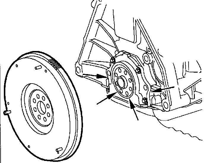
1. Remove transaxle, flywheel, cover and two lower oil pan bolts.
2. Pry tangs are located on both sides of the rear seal carrier. A rolling head prybar or pinch bar will separate the carrier from the cylinder block.
IMPORTANT: Screwdriver slots are provided to pry the seal out of the carrier. Use extreme care not to damage the crankshaft sealing surface. The tool SA9121E is used to install the seal and/or carrier. The tool prevents rolling the seal's lip.
DOHC (LL0) BLACK COMPOSITE CAM COVER
Removal
DOHC (LL0) engines are assembled with Black composite cam covers.

1. Remove Positive Crankcase Ventilation Valve (PVC) hose.
2. Remove cam cover fasteners.
3. Remove the cam cover assembly.
Installation
IMPORTANT:
- Inspect the cam cover isolations for cracks. Replace the isolators if deterioration exist.
- Gaskets over one year old may take a set and should be replaced. Gaskets under one year old do not need replacement. A small drop of RTV must be installed at the two T-joints whenever the cam cover is installed.

1. Install new cam cover gaskets, if removed.
2. Install the cam cover assembly.
3. Install the Positive Crankcase Ventilation Valve (PVC) hose.
RTV Removal And Surface Preparation
NOTICE: If excessive RTV is applied, or oil builds up in the blind holes, the casting will crack when bolts are installed.

Surfaces to be sealed must be clean and dry. RTV is removed from aluminum surfaces using scrapers, wire brush or Scotch-Brite Pads and disk (3M Clean-N Strip 2 inch D x 1/2 inch W x 1/4 inch center hole).
The cylinder block, head and front cover holes must be cleaned with a 3/16 inch drill and tap handle. The front cover non tapped holes can be cleaned with a 3/8 inch drill.
NOTICE: Do not use petroleum cleaners such as mineral spirits; they leave a film onto which RTV will not stick.

1. After all RTV is removed, clean the surfaces with a chlorinated solvent, such as carburetor spray cleaner, brake clean or alcohol Saturn P//N 21007432 (or equivalent) and Scotch-Brite Pad.
RTV Application And Component Installation
IMPORTANT: Only the Saturn recommended RTV (Saturn P/N 21006236 or equivalent) should be used. Surfaces to be sealed must be clean and dry. Reference appropriate torque valves.

1. Cut tube opening to approximately 2.0 mm (0.080 inch) inner diameter.

Apply the following RTV bead sizes to clean surfaces:
- Oil Pan: 4.0 mm (0.160 inch)
- Front Cover: 2.0 mm (0.080 inch)
- Rear Seal Carrier: 2.0 mm (0.080 inch)
- Cam Cover: 2.0 mm (0.080 inch)
a. T- joints.
b. When replacing procured gasket.

Follow each surface pattern and maintain the bead diameter cross sections required to ensure the joint is sealed.
IMPORTANT: Apply bead on the inside edge of the groove as shown.
2. Oil pan.

3. Make sure oil pump transfer port seals and front vibration damper/pulley seal are installed correctly.

IMPORTANT:
- The front cover oil seal drainback hole and passage way must be kept free of RTV to prevent front seal damage. After the front cover is installed, 6-12 squirts of oil can be pumped through the front oil seal drain back hole to make sure it is not plugged.
- Extra RTV is required at oil pan, cylinder head and cam/rocker cover T-joints to make sure gaps are filled to prevent oil leakage. The 1992 and later engines require a RTV bead around the top, center bolt hole.
4. Front cover.
IMPORTANT:
- Install a thin film of RTV sealant between the vibration damper/pulley assembly flange and washer only. The washer and bolt head flange are designed to prevent oil leakage and do not require sealant.
- The front cover, cylinder head and block holes must be cleaned with a 3/16 inch drill and tap handle. The front cover non tapped holes can be cleaned with a 3/8 inch drill.
NOTICE: To prevent engine front cover and mount damage, the three front upper mount to engine front cover nuts must be tightened down uniformly.
5. Install the two mount to midrail bracket nuts first. Next, install the three front upper mount to engine front cover nuts. Remove the block of wood from under the torque strut after the upper mount assembly is installed.
Upper Mount to Front Cover:
Torque: 50 Nm (37 ft. lbs.)
Upper Mount to Frame Rail Bracket:
Torque: 50 Nm (37 ft. lbs.)

6. Rear seal carrier.