7. Inspection of Piston and Connecting Rod Assemblies
- Tools Required
- SA9llOlE Feeler Gauge Set
- SA9178NE-A Dial Bore Gauge
IMPORTANT: The powdered metal connecting rod and cap are machined for the proper clearance. The connecting rod and cap must be used as an assembly with no repair or modifications to either mating surface.
Do not attempt to repair the connecting rod or the cap mating surfaces. If service is required, the connecting rod and cap must be replaced as an assembly.
1. Clean piston:
NOTICE: Do not damage the piston's aluminum surfaces during cleaning.
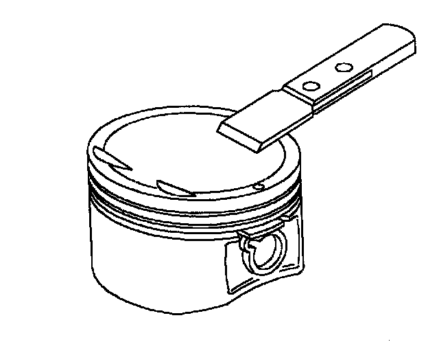
a. Using a gasket scraper, remove the carbon from the piston top.
b. Using a soft brush and solvent, thoroughly clean the piston.

c. Using a groove cleaning tool or broken ring, clean the ring grooves.

2. Inspect piston diameter and oil clearance:
a. Using a micrometer, measure the piston diameter at a right angle to the piston pin hole center line, 7 mm (0.27 inch) from the bottom of the piston.
Standard Piston Diameter:
Size:
Standard: 81.966 - 81.992 mm (3.2270 - 3.2280 inch)

b. Measure the cylinder bore diameter using a dial bore gauge, Service Tool SA9178NE (or equivalent) at two axis (transverse and longitudinal) 63.5 mm (2 1/2 inch) from top of block. Average the two measurements together for determining correct cylinder bore size and piston fit. Subtract the piston diameter (measured at 5 mm [0.200 inch] from the bottom of the piston) measurement from the cylinder bore diameter measurement.
Cylinder No. 2 and 3:
Standard: 0.000 - 0.044 mm (0.0000 - 0.0017 inch)
Service Limit: 0.070 mm (0.0028 inch) max.
Cylinder No. 1 and 4:
Standard: 0.008 - 0.054 mm (0.0003 - 0.0021 inch)
Service Limit: 0.070 mm (0.0028 inch) max.
If the clearance is greater than maximum, replace the piston. If necessary, hone or bore each cylinder required and replace the piston. If necessary, replace the cylinder block.

3. Inspect clearance between flank of piston ring groove and new piston ring.
a. Using a feeler gauge Service Tool SA91101NE (or equivalent), measure side clearance between new piston ring and the flank of the piston ring groove.
Ring Groove Clearance:
Standard: No. 1 Ring: 0.040 - 0.070 mm (0.0016 - 0.0028 inch)
Service Limit: No. 1 Ring: 0.090 mm (0.0035 inch) max.
Standard: No. 2 Ring: 0.030 - 0.080 mm (0.0012 - 0.0031 inch)
Service Limit: No. 2 Ring: 0.080 mm (0.0031 inch) max.
If the clearance is not within specification, replace the piston and rings.

4. Inspect piston ring end gap:
a. Insert the piston ring into the cylinder bore.
b. Using a piston, push the piston ring a little beyond the bottom of the ring travel (100 mm [3.94 inch]) from the top surface of the cylinder sleeve or block.
c. Using a feeler gauge SA91101NE (or equivalent), measure the end gap.
Standard End Gap:
Standard: No. 1 Ring: 0.18 - 0.33 mm (0.0071 - 0.0130 inch)
Service Limit: No. 1 Ring: 0.450 mm (0.0177 inch) max.
Standard: No. 2 Ring: 0.350 - 0.550 mm (0.0138 - 0.0216 inch)
Service Limit: No. 2 Ring: 0.650 mm (0.0256 inch) max.
Oil Ring (Side Rail):
Standard: 0.100 - 0.500 mm (0.0039 - 0.0197 inch)
Service Limit: 0.650 mm (0.0256 inch) max.
If the gap is greater than maximum, replace the piston ring.

5. Check piston pin bore diameter and pin diameter.
Pin Diameter:
Standard: 19.496 - 19.500 mm (0.7676 - 0.7677 inch)
Service Limit: 19.488 mm (0.7678 inch) min.
Piston Pin Bore Diameter:
Standard: 19.502 - 19.507 mm (0.7678 - 0.7680 inch)
Service Limit: 19.510 mm (0.7686 inch) max.
Oil Clearance:
Standard: 0.002 - 0.011 mm (0.0001 - 0.0004 inch)
Service Limit: 0.015 mm (0.0005 inch) max.
Oil the pin and push it into the piston with your thumb. The pin must rotate freely when centered in the piston pin bore.

6. Check connecting rod bushing and large end diameters:
Rod Bushing Diameter:
Standard: 19.420 - 19.506 mm (0.7670 - 0.7685 inch)
Service Limit: 19.526 mm (0.769 inch) max.
Large End Bore Diameter:
Standard: 50.193 - 50.207 mm (1.9761 - 1.9767 inch)
Service Limit: 50.207 mm (1.9767 inch) max.
7. Inspect connecting rods:
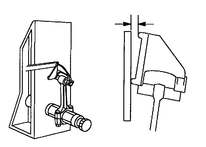
a. Using a rod aligner, check the connecting rod alignment. Check for bend.
Maximum bend per 100 mm (3.94 inch):
0.28 mm (0.011 inch) max.
If bend is greater than maximum, replace the connecting rod assembly.
b. Check for twist.
Maximum twist per 100 mm (3.94 inch):
0.320 mm (0.0126 inch) max.
If twist is greater than maximum, replace the connecting rod assembly.
IMPORTANT: When replacing the connecting rod, always replace the bearings.