Powertrain Assembly Removal
Engine Replacement
Tools Required
^ SA9105E 3-Bar Engine Support Fixture
^ SA9412G Constant Force Clamp Pliers
^ SA9127E Gauge Bar Set
Powertrain Assembly Removal Procedure

Caution: Do not allow smoking or the use of open flames in the area where work on the fuel or EVAP system is taking place. Anytime work is being done on the fuel system, disconnect the negative battery cable, except for those tests where battery voltage is required.
1. Disconnect negative battery cable and remove coolant bottle cap.
Notice: The engine's cooling system thermostat and water pump will not function correctly if oil is found in the cooling system. The cooling system must be flushed and the water pump and the thermostat's cartridge replaced.
2. Drain engine coolant. Drains are located at right front corner of the engine block and right hand side of radiator.
3. Remove air induction system inlet hose or air cleaner assembly. Cover the throttle body opening with a shop towel.

4. Disconnect electrical and vacuum connectors where applicable:
^ The engine coolant temperature (ECT) sensor.
^ The oxygen sensor and clip at transaxle front mount bracket.
^ The idle air control (IAC) valve.
^ The ignition coil - 2 different connectors.
^ The throttle position (TP) sensor.
^ The MAP sensor.
^ The EGR solenoid. The brake booster hose at brake booster or intake manifold.

^ Ground connectors, 2, located at transaxle attachment studs at rear side of cylinder block.
^ Injector connectors.

Important: The transaxle electrical connectors and shift cables can also be removed after the vehicle is on a hoist and the left-hand side splash shield is removed.
^ Automatic/manual transaxle connectors:
- The neutral safety/selector switch, 3 connectors.
- The valve body actuator connector.
- The turbine speed sensor.
- The transaxle temperature sensor.
- The back-up light switch, manual transaxle.

5. Disconnect accelerator cable assembly.
Caution: Catch leaking fuel in a container whenever fittings are loosened or lines are disconnected.
6. Disconnect the fuel line.
6.1. Fuel pressure can be bled into an approved container using the SA9127E.

6.2. Disconnect the fuel supply line. Fuel line can be tied to brake master cylinder lines to prevent fuel spill.
7. Disconnect the upper radiator hose at cylinder head outlet and deaeration hose at engine.

Important: It is not necessary to discharge the A/C compressor during powertrain removal.
8. Remove A/C compressor, if equipped, bolts and tie the compressor to the front crossbar. Leave both A/C mounting brackets mounted on the engine.
Important: Pinch the plastic connector tabs and pull on the line. Wrap the end of the lines in a clean shop towel to prevent debris entry.
9. Disconnect the automatic transaxle cooler lines at transaxle and plug.

10. Disconnect the automatic transaxle shifter cable.

11. Manual transaxle shifter cables and clutch hydraulic system.
11.1. Remove the 2 hydraulic damper to clutch housing stud nuts and slide damper and bracket assembly off studs.
11.2. Rotate clutch actuator 1/4 turn counter clockwise while pushing toward housing to disen(gauge) the bayonet connector and remove from clutch housing.
11.3. Tie clutch hydraulic system to battery tray. Do not kink or pinch the nylon hydraulic lines.

12. Using safety wire or plastic tie straps, tie the radiator, condenser, and fan module to the front vehicle crossbar. The safety wire or plastic tie straps can be routed around the two fan shroud supports and around the crossbar.

Caution: Ensure that the vehicle is properly supported and squarely positioned. To help avoid personal injury when a vehicle is on a hoist, provide additional support for the vehicle on the opposite end from which the components are being removed.
13. Jack or raise the vehicle squarely on a hoist. Reference the lift instructions for positioning the vehicle correctly on the hoist.
14. Remove the front wheels and shield attachment fasteners from the cradle.

15. Remove the brake caliper bracket attachment bolts, 2 on each side, and tie the caliper assemblies to the shock tower springs using safety wire or plastic tie straps. Shock assemblies and springs remain with the body.
16. Remove both strut to knuckle attachment bolts, 2 on each side, and allow the knuckle and hub assembly to remain with the cradle. The stabilizer bar remains attached to the cradle and lower control arms.

17. Disconnect the lower radiator and heater return hoses at the engine. Use the SA9412G, Snap-On Tool HCP10, or equivalent.
18. Disconnect the heater inlet hose at the front of the dash or engine.
19. Disconnect the steering shaft and power steering pressure switch electrical connector at the gear, if applicable.

Notice: Intake and exhaust manifold stud threads can be damaged during removal and must be replaced when a new machined cylinder head casting is installed.
20. Disconnect the engine front exhaust pipe at the exhaust manifold, catalytic converter, and powertrain stiffening bracket.
21. Remove the automatic transaxle flywheel cover and torque converter to flexplate bolts, if applicable.

22. Disconnect the electrical and vacuum connections:
22.1. Starter -- solenoid and battery feed
22.2. Generator -- field and battery feed
22.3. Oil pressure sensor
22.4. Knock sensor
22.5. Crankshaft position sensor
Important: The EVO solenoid connector is also accessible from underhood on vehicles with the SOHC (L24) engine.
22.6. EVO solenoid, if equipped
22.7. Vehicle speed sensor
22.8. EVAP canister purge solenoid
22.9. PCM and oxygen sensor
22.10. ABS wheel sensor connector grounds, if equipped

23. Unclip the brake lines from the rear side of the cradle.

24. Carefully remove the electrical harness from the engine. Lower the vehicle enough on the hoist to lay the electrical harness on top of the underhood junction block and battery cover.
Important: Installation of the wood block prior to upper engine torque axis mount removal allows the mount to be easily installed without lifting or jacking the powertrain.
25. Place a 1 in. x 1 in. x 2 in. long block of wood between the torque strut and cradle.

26. Remove the 3 right-hand, upper engine torque axis mount to front cover nuts and the 2 mount to midrail bracket nuts, allowing the powertrain to rest on the block of wood.
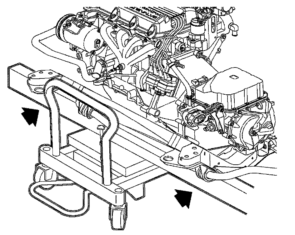
27. Place the powertrain support dolly under the cradle. Use 2 4 in. x 4 in. x 36 in. blocks of wood to support the cradle on the dolly.
28. Remove the 2 right-hand, front engine mount torque strut brackets to cradle nuts.
29. Remove the 4 cradle attachment bolts and carefully lower the complete powertrain assembly from the vehicle or raise the vehicle off of the powertrain assembly.

30. Remove spark plug wire ends at ignition module.
31. Remove power steering pump with support bracket, if equipped. Attach pump to frame or steering gear in an upright position with safety wire.
32. Attach the SA9105E or equivalent to the engine service support brackets for powertrain support.

33. Place a 1/2 in. x 1 in. x 3 in. block of wood under the axle shaft. Remove intake manifold support brace (DOHC [LL0]) and three axle shaft bracket support bolts and allow bracket to rotate rearward. It may be necessary to lift the engine slightly to allow for clearance between the drive axle shaft bracket and starter support bracket.

34. Place a 4 in. x 4 in. x 6 in. long block of wood under the transaxle housing for support.

35. The engine strut bracket and torque strut are removed as an assembly. The engine may have to be lifted slightly for engine strut assembly removal.

Important: Manual transaxles require the engine be moved approximately 100 mm (4 in) forward in the cradle for input shaft disen(gauge)ment.
36. Remove the 4 transaxle housing attachment bolts.
Important: Before shipment, all fluids must be drained from the engine, and all openings plugged or capped.
37. Carefully lift the engine assembly from the frame and mount it on an engine stand for repairs or on a transportation pallet.