Instrument Panel (IP) - Installation Procedure
INSTALLATIONIMPORTANT: Make sure wiring harnesses and instrument panel fuse block (IPFB) are in position.
1. Install instrument panel retainer assembly.
2. Install I/P retainer assembly to dash panel assembly bolts and nuts. Do not torque bolts and nuts.

3. Install instrument panel fuse block (IPFB) to H-Brace.
4. Install ground wires with fastener to H-Brace.
Torque:
Ground Wire-to-H-Brace: 2.2 N.m (19 in-lbs)
5. Install radio ground strap and fastener through H-Brace to junction block.
Torque:
Radio Ground Strap-to-H-Brace: 2.2 N.m (19 in-lbs)
6. Return I/P harness plastic retainer to H-Brace.

7. Install H-Brace bolts to front floor bracket.
Torque:
H-Brace-to-Floor Panel Bolts: 25 N.m (19 ft-lbs)
IMPORTANT: Do not connect passenger side inflator restraint harness connectors at this time.

8. Route passenger side inflatable restraint harness through retainer assembly. Close harness retainer assembly clip.
IMPORTANT: Do not connect passenger side inflator restraint harness connector at this time.

9. For RHD domestic, route harness through retainer assembly and clip electrical connector to retainer assembly.

10. Position passenger side inflatable restraint retainer assembly.
11. Install passenger side inflatable restraint ensuring the retaining tabs are engaged to the I/P reinforcement assembly.
12. Install passenger side inflator restraint bolts.
Torque:
Passenger Side Inflator Module Bolts: 10 N.m (89 in-lbs)

13. Torque I/P retainer assembly bolts and nuts.
Torque:
I/P Retainer Assembly Bolts: 10 N.m (89 in-lbs)

14. Connect antenna cable and secure to lower right side of instrument panel retainer assembly.

15. Install passenger side inflatable restraint cover.
Torque:
Passenger Side Inflator Module Cover Fasteners: 2.2 N.m (19 in-lbs)

16. Install I/P compartment:
16.1 Position I/P compartment door assembly to retainer assembly.
16.2 Install I/P compartment door pins into instrument panel retainer assembly.
16.3 Lift I/P compartment enough to install UP compartment door stop assemblies.
16.4 Close I/P compartment door.

17. Raise steering column into position.
18. Install and torque bolts.
Torque:
Steering Column-to-I/P Bolts: 35 N.m (26 ft-lbs)
IMPORTANT: Make sure wiring harnesses do not interfere with control lever movement.
Cable identification:
^ Temperature cable - white
^ Mode cable - black

19. Install HVAC controller:
19.1 Install mode valve cable onto mode valve pin.
19.2 Snap slot on cable into HVAC controller base.
19.3 Repeat steps for temperature cable.

19.4 Install blower switch connector.
19.5 Install HVAC controller harness.
19.6 Install and torque fasteners.
Torque:
HVAC Control Head-to-I/P Fasteners: 2.5 N.m (22 in-lbs)

20. Install radio:
20.1 Connect radio ground strap spade terminal.
20.2 Connect electrical connectors.
20.3 Connect antenna lead.
20.4 Install radio by sliding it into guides on instrument panel.
20.5 Install and torque fasteners.
Torque:
Radio-to-I/P Fasteners: 2.5 N.m (22 in-lbs)

21. Install instrument cluster:
21.1 Place tabs on bottom of I/P cluster into retainer assembly.
21.2 Install fasteners.
Torque:
I/P Cluster-to-I/P Housing Fasteners: 2.2 N.m (19 in-lbs)
21.3 Connect electrical connector to instrument panel cluster.

22. Install I/P cluster bezel:
22.1 Place dimmer/traction control switch connector through bezel opening.
22.2 Position I/P cluster bezel by lining up clip location.
22.3 Snap I/P cluster bezel in place by pushing at clip locations.

23. Position upper steering column shroud.
24. Position lower steering column shroud and install fasteners.
Torque:
Steering Column Shroud Fasteners: 1.5 N.m (13 in-lbs)

25. Install ignition bezel:
25.1 Align peg of ignition bezel with the cut out in lower shroud.
25.2 Snap into place.

26. Connect dimmer/traction control switch wiring harness (if equipped).
27. Install dimmer/traction control dimmer switch.

28. Connect left and right doorjamb switch connectors.
IMPORTANT: Ensure that endcap bottom portions are inside of the filler panel and I/P compartment assemblies.
29. Install left and right endcap assemblies:
29.1 Maneuver the assemblies past inner UP retainer assembly and weatherstrips.
29.2 Snap clips into I/P retainer assembly locations.
29.3 Install fasteners.
Torque:
I/P Endcap-to-I/P Fasteners: 2.2 N.m (19 in-lbs)

30. Install data link connector.
31. Route hood release cable through I/P and install cable to lever.

For RHD Domestic:
32. Install hood release handle assembly. Install hood release handle fasteners.

33. Install steering column filler panel.
Torque:
Steering Column Filter Panel Fasteners: 2.2 N.m (19 in-lbs)

34. Install console:
34.1 Apply park brake.
34.2 Adjust front seats to most rearward position.
34.3 Recline driver's and passenger's seat backs as far down as possible.
34.4 Select neutral for transaxle gear (on automatic transaxles).
34.5 Hold front end of console down and rear end up.
34.6 Position all harnesses so they can be accessed.
34.7 Maneuver console over gear selector lever and past brake lever.
34.8 Connect power outlet electrical connector.

34.9 On automatic transaxle equipped vehicles, remove tape from gear selector.
34.10 Install fasteners at rear of console.
Torque:
Console Rear Fasteners: 2.2 N.m (19 in-lbs)

34.11 Install and torque front console fasteners.
Torque:
Console Front Fasteners: 2.2 N.m (19 in-lbs)

34.12 Install left and right extension panels by inserting hinges into console.
34.13 Rotate closed and push in at dual lock locations.
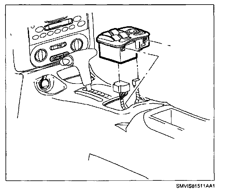
35. Connect power window switch connector (if equipped).
36. Install power window switch or storage tray (depending on equipment).
If Equipped:
37. Enable head curtain inflator module.
NOTE: Be careful not to damage VIN plate when removing or replacing I/P upper trim panel.
IMPORTANT: Be sure upper trim panel seal is correctly seated on forward edge before installing upper trim panel.

38. Install I/P top cover:
38.1 Position upper trim panel on retainer assembly.
38.2 Align position tabs and clips with receiving locations in retainer assembly.
38.3 Snap in clips at clip locations.
38.4 Install fasteners on underside of upper trim panel on passenger side of vehicle.
Torque:
I/P Upper Trim Panel Fasteners: 6 N.m (53 in-lbs)
39. Enable passenger supplemental inflatable restraint system.