Instrument Panel Assembly Replacement (LHD Shown, RHD Similar)
Instrument Panel Assembly Replacement (LHD Shown, RHD Similar)
Removal Procedure

1. Disable the SIR System. Refer to Disabling the SIR System in SIR.
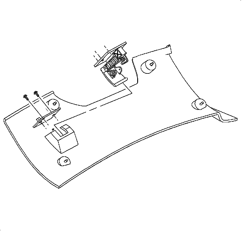
2. Remove the I/P top cover.
1. Remove the screws located under the upper trim panel on the passenger's side of the vehicle.
Important: Be careful not to damage the VIN plate when removing or replacing the instrument panel upper trim.
2. Disengage the clips at locations by grasping the edges of the upper trim panel and lifting up.
3. Disengage the velcro pads from the attachments at the rear of the upper trim panel by reaching under the panel and lifting straight up.
4. Raise the upper trim panel enough to clear the VIN plate.
3. Disable the head curtain inflator module, if equipped. Refer to Disabling the SIR System in SIR.
4. Apply the parking brake lever.

5. Remove the window/mirror switch, if equipped.
1. Exert pressure on the rear with your hand.
2. Using a small flat blade screwdriver, carefully lift the switch.

3. Lift up and out.
4. Disconnect the electrical connectors by locating the retention tabs and disengaging the connectors.

6. Remove the console.
1. Select neutral for the transaxle gear on automatic transaxles.
2. Adjust the front seats to the maximum forward position.
3. Remove the rear console fasteners.

4. Adjust the front seats to the maximum rear position.
5. Remove the left and right lower trim panel extensions by pulling outward at the dual lock locations.
6. Rotate the panels outward to disengage the hinges from the console.
7. Remove the front console fasteners.

8. Move the console rearward.
9. Disengage the retaining tabs and disconnect the power outlet connector.
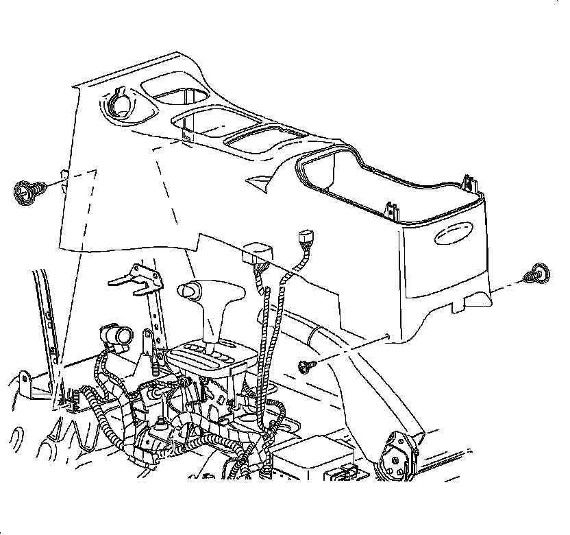
10. On automatic transaxle equipped vehicles, press and tape the gear selector button IN to clear the shifter opening.
11. Maneuver the console beyond the gear selector and the parking brake by lifting the rear of the console.
12. Remove the console from the vehicle.

7. Remove the steering column filler panel fasteners.

8. Remove the hood release cable from the lever by releasing the cable housing, then rotating the cable downward to the cutout.
9. For RHD hood release, remove the hood release handle assembly screws.
10. Remove the hood release handle assembly.
11. Remove the steering column filler panel.
12. Remove the data link connector.
Notice: Do not remove weatherstrips. Adhesion will be lost if removed.

13. Remove the left and right endcap assemblies.
1. Remove the fasteners.
2. Carefully disengage the clips at the I/P retainer assembly locations. Using a blunt tool will aid in disengaging the clips.
3. Maneuver the assemblies past the inner I/P retainer assembly and weatherstrips.
14. Remove the wiring harness from the door jamb switch.

15. Remove the dimmer/traction switch assembly:
1. Use a blunt tool to pry and depress the retaining tab on the left side of the switch housing.
2. Depress the wiring connector tabs and remove the harnesses from the switch.

16. Gently pry the edges of the ignition lock bezel with a blunt tool and separate from the lower shroud.

17. Remove the fasteners and lower the steering column shroud.
18. Lift and remove the upper shroud from the steering column.
19. Lower the steering column by pushing down on the steering column adjusting handle.

20. Remove the I/P cluster bezel by disengaging the clips from the retainer assembly, grasping the edges of the bezel near the clip locations, and pulling outward.

21. Remove the I/P cluster:
1. Remove the fasteners.
2. Disconnect the electrical connector from the I/P cluster by squeezing the tabs on each side of the connector.

22. Remove the radio.
1. Remove the radio fasteners.
2. Pull the radio out slightly to access the rear.
3. Disconnect the electrical connector, antenna, and ground strap connector.

23. Remove the HVAC controller:
1. Remove the fasteners.
2. Disconnect the HVAC control head connector.

3. Remove the temperature cable by squeezing the lock tabs together while pulling the coiled end of the cable straight up beyond the retaining tabs.
4. Remove the mode cable by squeezing the lock tabs together while pulling the coiled end of the cable straight up beyond the retaining tabs.

24. Disengage the metal clip from the door jamb switch wiring harness retainer. Remove the left and right harnesses from the I/P retainer assembly.

25. Disengage the dimmer/traction control switch wiring harness from the retainer assembly.

26. Remove the steering column bolts and lower the column on the front seat.

27. Remove the I/P compartment.
1. Open the I/P compartment door.
2. Turn the right and left I/P compartment door stop assemblies to release the door and compartment assembly from the I/P retainer assembly.
Important: The lower I/P door pins are on the right and left outside edges at the base of the compartment.
3. Push the lower I/P door pins from the outside of the door to inside the I/P compartment.

28. Remove the fasteners and passenger's side inflatable restraint cover.

29. Disengage the antenna lead.

30. Remove the H-Brace to front floor bracket assembly bolts.

31. Remove the passenger's side inflatable restraint:
1. Unclip the plastic retainer and lift the passenger side inflatable restraint harness from the cowl support.

2. For RHD domestic vehicles:
Remove the clip from the retaining assembly.

3. Remove the fasteners located underneath the passenger side inflatable restraint.
4. Pry the retaining tabs outward that retain the passenger side inflatable restraint to the I/P retainer assembly.
5. Remove the passenger side inflatable restraint from the opening.

32. Remove the I/P harness plastic retainer from the H-Brace.
33. Remove the fasteners and ground wires from the H-Brace.
34. Remove the radio ground strap from the H-Brace.
35. Remove the instrument panel fuse block (IPFB).

Important: Use the illustration to determine the fastener location and the direction of removal.
36. Remove the I/P fasteners and nuts.
Notice: Put I/P retainer assembly on a clean surface so that the assembly surface does not become damaged.
37. Remove the I/P retainer assembly from the vehicle.
Installation Procedure
Important: Make sure the wiring harnesses and instrument panel fuse block (IPFB) are in position.
1. Install the instrument panel retainer assembly.
2. Install the I/P retainer assembly to the dash panel assembly bolts and nuts. Do not torque the bolts and nuts.
3. Install the instrument panel fuse block (IPFB) to the H-Brace.
Notice: Refer to Fastener Notice in Cautions and Notices.
4. Install the ground wires with a fastener to the H-Brace.
Tighten the ground wire-to-H-brace to 2.2 Nm (19 lb in).
5. Install the radio ground strap and fastener through the H-Brace to the junction block.
Tighten the radio ground strap-to-H-brace to 2.2 Nm (19 lb in).
6. Return the I/P harness plastic retainer to the H-Brace.
7. Install the H-Brace bolts to the front floor bracket.
Tighten the H-brace-to-floor panel bolts to 25 Nm (19 lb ft).
Important: Do not connect the passenger side inflator restraint harness connectors at this time.
8. Route the passenger side inflatable restraint harness through the retainer assembly. Close the harness retainer assembly clip.
Important: Do not connect the passenger side inflator restraint harness connector at this time.
9. For RHD domestic vehicles, route the harness through the retainer assembly and clip the electrical connector to the retainer assembly.
10. Position the passenger side inflatable restraint retainer assembly.
11. Install the passenger side inflatable restraint ensuring the retaining tabs are engaged to the I/P reinforcement assembly.
12. Install the passenger side inflator restraint bolts.
Tighten the passenger side inflator module bolts to 10 Nm (89 lb in).

13. Torque the I/P retainer assembly bolts and nuts.
Tighten the I/P retainer assembly bolts to 10 Nm (89 lb in).
14. Connect the antenna cable and secure to the lower right side of the instrument panel retainer assembly.
15. Install the passenger side inflatable restraint cover.
Tighten the passenger side inflator module cover fasteners to 2.2 Nm (19 lb in).
16. Install the I/P compartment:
1. Position the I/P compartment door assembly to the retainer assembly.
2. Install the I/P compartment door pins into the instrument panel retainer assembly.
3. Lift the I/P compartment enough to install the I/P compartment door stop assemblies.
4. Close the I/P compartment door.
17. Raise the steering column into position.
18. Install and torque the bolts.
Tighten the steering column-to-I/P bolts to 35 Nm (26 lb ft).
Important: Make sure the wiring harnesses do not interfere with the control lever movement.
19. Install the HVAC controller:
* The temperature cable is white.
* The mode cable is black.
1. Install the mode valve cable onto the mode valve pin.
2. Snap the slot on the cable into the HVAC controller base.
3. Repeat the steps for the temperature cable.
4. Install the blower switch connector.
5. Install the HVAC controller harness.
6. Install and torque the fasteners.
Tighten the HVAC control head-to-I/P fasteners to 2.5 Nm (22 lb in).
20. Install the radio.
1. Connect the radio ground strap spade terminal.
2. Connect the electrical connectors.
3. Connect the antenna lead.
4. Install the radio by sliding it into the guides on the instrument panel.
5. Install and torque the fasteners.
Tighten the radio-to-I/P fasteners to 2.5 Nm (22 lb in).
21. Install the instrument cluster.
1. Place the tabs on the bottom of the I/P cluster into the retainer assembly.
2. Install the fasteners.
Tighten the I/P cluster-to-I/P housing fasteners to 2.2 Nm (19 lb in).
3. Connect the electrical connector to the instrument panel cluster.
22. Install the I/P cluster bezel.
1. Place the dimmer/traction control switch connector through the bezel opening.
2. Position the I/P cluster bezel by lining up the clip location.
3. Snap the I/P cluster bezel in place by pushing at the clip locations.
23. Position the upper steering column shroud.
24. Position the lower steering column shroud and install the fasteners.
Tighten the steering column shroud fasteners to 1.5 Nm (13 lb in).
25. Install the ignition bezel.
1. Align the peg of the ignition bezel with the cut out in the lower shroud.
2. Snap into place.
26. Connect the dimmer/traction control switch wiring harness, if equipped.
27. Install the dimmer/traction control dimmer switch.
28. Connect the left and right door jamb switch connectors.
Important: Ensure that the endcap bottom portions are inside of the filler panel and I/P compartment assemblies.
29. Install the left and right endcap assemblies:
1. Maneuver the assemblies past the inner I/P retainer assembly and weatherstrips.
2. Snap the clips into the I/P retainer assembly locations.
3. Install the fasteners.
Tighten the I/P endcap-to-I/P fasteners to 2.2 Nm (19 lb in).
30. Install the data link connector.
31. Route the hood release cable through the I/P and install the cable to the lever.
32. For RHD domestic vehicles:
Install the hood release handle assembly.
33. Install the hood release handle fasteners.
34. Install the steering column filler panel.
Tighten the steering column filler panel fasteners to 2.2 Nm (19 lb in).
35. Install the console.
1. Apply the park brake.
2. Adjust the front seats to the maximum rear position.
3. Recline the driver's and passenger's seat backs as far down as possible.
4. Select neutral for the transaxle gear on automatic transaxles.
5. Hold the front end of the console down and the rear end up.
6. Position all of the harnesses so they can be accessed.
7. Maneuver the console over the gear selector lever and past the brake lever.
8. Connect the power outlet electrical connector.
9. On automatic transaxle equipped vehicles, remove the tape from the gear selector button.
10. Install the fasteners at the rear of the console.
Tighten the console rear fasteners to 2.2 Nm (19 lb in).

11. Install and torque the front console fasteners.
Tighten the console front fasteners to 2.2 Nm (19 lb in).
12. Install the left and right extension panels by inserting the hinges into the console.
13. Rotate closed and push in at the dual lock locations.
36. Connect the power window switch connector, if equipped.
37. Install the power window switch or storage tray, depending on the equipment.
38. Enable the head curtain inflator module, if equipped. Refer to Enabling the SIR System in SIR.
Notice: Be careful not to damage the VIN plate when removing or replacing the upper trim panel.
Important: Ensure that the upper trim panel seal is correctly seated on the forward edge before installing the upper trim panel.
39. Install the I/P top cover:
1. Position the upper trim panel on the retainer assembly.
2. Align the position tabs and clips with the receiving locations in the retainer assembly.
3. Snap in the clips at the clip locations.
4. Install the fasteners on the underside of the upper trim panel on the passenger side of the vehicle.
Tighten the I/P upper trim panel fasteners to 6 Nm (53 lb in).
40. Enable the passenger supplemental inflatable restraint system. Refer to Enabling the SIR System in SIR.