Assembly
TOOLS REQUIRED- SA9l12T Differential End Play Gauge
- SA9113T Axle Seal Installer (Driver Handle Included)
- SA9119T Input Shaft Holding Tool
- SA9137T Servo Piston Seal Installer/Sizer
- SA9143T Input Shaft Seal Installer
- SA9163T Converter Endplay Tool

1. Install case to converter housing gasket.
IMPORTANT: Clean case and housing surfaces, use sealant Loctite 515(r) (Saturn P/N 21005993) or equivalent. Apply onto both sides of gasket or case halves using a small roller.
2. Check to make sure the oil pump O-ring, reverse drive gear thrust washer, reverse driven gear thrust washer and park lever rod are in position before installing the case.

3. Install the transaxle case, lower case over the shafts and work down onto the differential bearing. It may be necessary to turn the reverse idler gear so case can fit all the way down on the converter housing.
IMPORTANT: Clean and lubricate fasteners with Saturn Transaxle Fluid. Wipe off excess fluid.
IMPORTANT: Two bolts are on the torque converter side of the housing. Do not turn transaxle over until 1st gears are installed.

4. Install the case to converter housing bolts using torque sequence:
Torque:
Case-to-Converter Housing (Short Bolts): 25 Nm (18 ft. lbs.)
Torque:
Case-to-Converter Housing (Long Bolts): 28 Nm (21 ft. lbs.)
5. Check to make sure both shafts rotate freely.
6. Measure differential end play by using Differential End Play Gauge SA9112T. Select the largest gauge tool that will fit between the case bearing pocket and the outer differential race.

7. Use the part number on the tool to choose and install the correct snap ring.
IMPORTANT: Prior to using Axle Seal Installer (Driver Handle Included) SA9113T inspect the tool for any nicks Or burrs that could damage the seal lip.
8. Apply Loctite 515(r) Gasket Eliminator sealant (Saturn P/N 21005993) or equivalent to area of axle seal that mates to case and install the case side axle seal using tool SA9113T.
9. Install axle seal retainer (snap ring).

10. Install forward/reverse servo piston seal if necessary.
IMPORTANT: Prior to using Input Shaft Seal Installer SA9143T and Servo Piston Seal Installer/Sizer SA9137T inspect the tool for any nicks or burrs that could damage the forward/reverse servo piston seal.
10.1 Place servo piston on seal installer Backup Base SA9137T-2 (3).
10.2 Install Expander SA9137T-1 (2) to servo piston.
10.3 Lube seal ring and position on expander cone.
IMPORTANT: Lube seal with Saturn Transaxle Fluid before installation.
10.4 Use Input Shaft Seal Installer SA9143T (1) to install seal.

10.5 Place servo piston on seal sizer Holding Base SA9137T-4 (2).
10.6 Size seal by placing Sizing Ring SA9137T-3 (1) over piston, with large internal diameter down until it bottoms out on work table.
11. Slide the fwd/reverse fork onto the second reverse sleeve.
IMPORTANT: When installing servo piston, lube seal and use care not to roll or cut seal while inserting into bore. If servo piston is being replaced, be sure current part is used.

12. Insert the fwd/reverse servo piston into the bore and line up fork and servo shaft as servo is pushed in. Before pushing the servo all the way in, align counter bore bolt hole in servo with hole in fork. The flat on the servo shaft should face the valve body opening in the case.
13. Clean bolt threads and apply Loctite 242(r) Thread locker (Saturn P/N 21485277) or equivalent on bolt threads.
14. Install fork to servo piston bolt and torque.
Torque:
Forward/Reverse Shift Fork-to-Forward/Reverse Servo Piston Bolt: 10 Nm (89 inch lbs.)
15. Install servo spring.
IMPORTANT: Clean and lubricate fasteners with Saturn Transaxle Fluid. Wipe off excess fluid. Do not use fasteners to pull cover down.
16. Install servo cover O-ring seal to cover and install cover. Torque two bolts.
Torque:
Forward/Reverse Servo Piston Cover-to-Case Bolts: 20 Nm (15 ft. lbs.)
17. Install 1st driven gear and sprag assembly.
18. Install 1st driven gear thrust washer.
19. Move park pawl actuator rod to engage parking pawl.
NOTICE: Use a new nut due to insufficient torque retention of old nut. Clean shaft threads with a wire brush. When tightening and torquing this nut it must be done with a hand wrench or torque wrench. Using a power tool will generate excess heat in the fastener causing a incorrect torque.
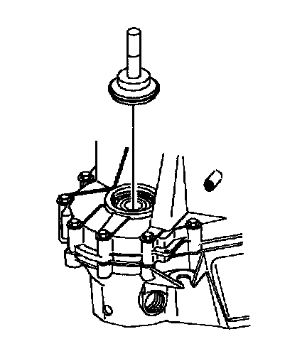
20. Hand start the output shaft clamp nut. Run down with a torque wrench.
Torque:
Output Shaft Clamp Nut: 150 Nm (111 ft. lbs.)

21. Lay 1st clutch housing on flat surface.
NOTICE: Make sure tabs on 1st gear thrust washer line up with slots on the 1st clutch housing assembly hub or damage to the 1st gear thrust washer will occur.
IMPORTANT: Chamfer side goes toward the clutch housing and flat side goes toward 1st gear.
22. Apply a generous amount of petroleum jelly to hold the 1st gear thrust washer in place and install the 1st gear thrust washer on the 1st clutch housing assembly hub.
23. Install thrust bearing with rollers (down) toward 1st gear thrust washer.
24. Install 1st clutch, clutch (needle) bearing.
25. Install 1st drive gear and hub assembly into 1st clutch housing assembly by twisting the gear to align the gear hub with the clutch tangs.
26. When installing the 1st drive gear and hub assembly into the clutch pack, rotate the gear and hub assembly back and forth to align the clutch plates. If you are not sure that all of the clutch plates have been engaged, lift the gear out of the clutch housing and verify that all clutch tangs are aligned.
27. Install 1st gear thrust washer.
NOTICE: If assembly is not held together, the gear hub may slide out of the clutch housing which may allow the 1st gear thrust washer to move out of location or allow clutch plates to be pinched when the input shaft nut is torqued.
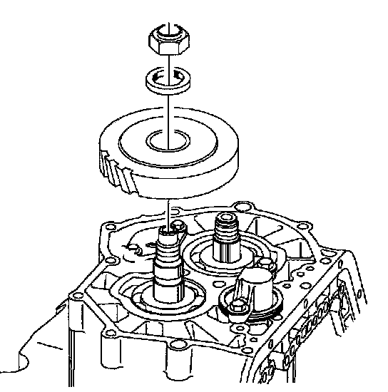
28. Hold the 1st gear and clutch assembly together and install on the input shaft.
29. Install 1st gear and hub assembly, and 1st clutch housing assembly on the input shaft.

30. Install the Input Shaft Holding Tool SA9ll9T.
NOTICE: Use a new nut due to insufficient torque retention of old nut. Clean shaft threads with a wire brush. When tightening and torquing this nut it must be done with a hand wrench or torque wrench. Using a power tool will generate excess heat in the fastener causing a incorrect torque.
31. Hand start the input shaft clamp nut. Run the nut down with a torque wrench.
Torque:
Input Shaft Clamp Nut: 150 Nm (111 ft. lbs.)
NOTICE: After the input and output shaft nut have been installed, verify proper operation.
IMPORTANT: To verify 1st clutch assembly, gear and hub are positioned properly, check clearance between 1st drive gear and bearing.
31.1 Engage park pawl.
Clearance:
Standard: 0.075 - 0.425 mm (0.003 - 0.017 inch)
31.2 Rotate the input shaft by turning the 1st clutch housing. The clutch housing should turn freely in both directions.
^ If input shaft turns freely in one direction only, the 1st clutch is binding.
^ If input shaft will not turn freely in either direction, 2nd, 3rd, or 4th clutch is binding.
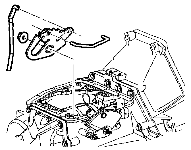
32. Connect the manual valve link to the manual detent lever.
33. Insert the manual detent and link into the transaxle, and connect the park lever actuator rod to the detent lever.
34. Hold the detent lever in position and slide the manual detent lever shaft through the case and detent lever.
35. Line up the flats on the manual detent lever with the flats on the manual detent shaft and install the attachment nut.
Torque:
Manual Detent Lever-to-Manual Detent Shaft Nut: 12 Nm (9 ft. lbs.)

36. Install the transaxle range switch and retaining bolts; do not tighten at this point.
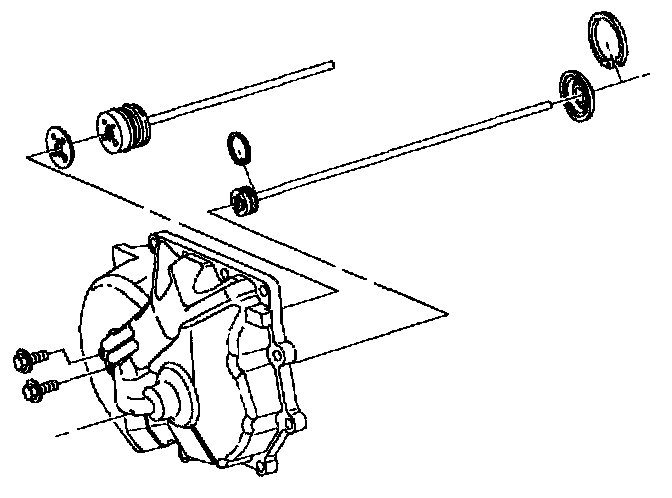
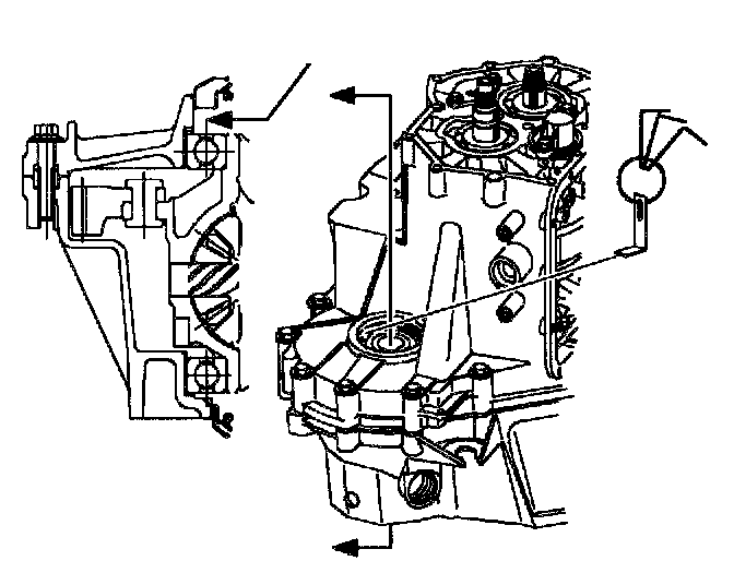
37. Install new end cover gasket onto clean surface of case. (1st Design shown, 2nd Design similar)
IMPORTANT: Do not use force as tube can bend easily. Rotate the shafts to align the tubes.
38. Install the end cover to the transaxle case. Insert the input and output shaft tubes into the ends of the shafts and lower cover. If the cover does not seat, turn the input and output shafts to help align the tubes with the bushings in the shafts.
IMPORTANT: Clean and lubricate fasteners with Saturn Transaxle Fluid. Wipe off excess fluid.
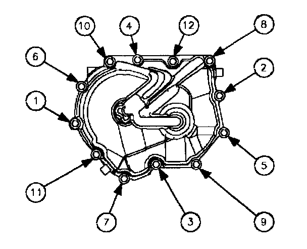
39. Install the end cover to case bolts and torque using torque sequence.
Torque:
End Cover-to-Case Bolts: 28 Nm (21 ft. lbs.)

40. To verify proper assembly, air check clutches and servo before installing valve body.
41. Turn the transaxle, valve body side up.
NOTICE: Prior to using seal installer SA9113T inspect the tool for any nicks or burrs that may damage the seal lip.
42. Apply Loctite 515(r) Gasket Eliminator sealant P/N 21005993 or equivalent to area of seal that mates to housing and install the converter housing axle seal using Axle Seal Installer SA9113T. (Driver Handle included.)
IMPORTANT: Clean and lubricate fasteners with Saturn Transaxle Fluid. Wipe off excess fluid.
43. Install two converter housing to case bolts.
Torque:
Case-to-Converter Housing (Short Bolts): 25 Nm (18 ft. lbs.)

44. Install drain plug.
Torque:
Transaxle Drain Plug: 30 Nm (22 ft. lbs.)
45. Air check reverse/servo piston assembly.

46. Install manual valve link in manual valve and install the valve body assembly. The valve body has two dowel bolts that assist in aligning valve body to case. For reference, the bolts are identified in the illustration below:
1) Valve body-to-case dowel bolts
2) Upper-to-lower valve body dowel bolts
3) Bolt holding upper and lower valve body
47. Lower valve body and insert manual link into manual valve.
IMPORTANT: Clean and lubricate fasteners with Saturn Transaxle Fluid. Wipe off excess fluid and install.
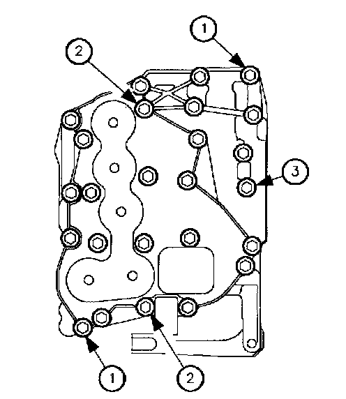
48. Torque valve body-to-case bolts in the sequence shown below.
Torque:
Valve body Assembly Bolts: 11 Nm (8 ft. lbs.)
IMPORTANT: While adjusting the transaxle range switch, always rotate the switch towards the engine to achieve continuity. A diagnostic trouble code P0706 could result if this procedure is not followed.
IMPORTANT: Digital volt/ohmmeter (DVOM) with audible continuity test is preferred. Do not stick probe in transaxle range switch terminal hole; use male terminals on transaxle range switch or faulty readings could occur.

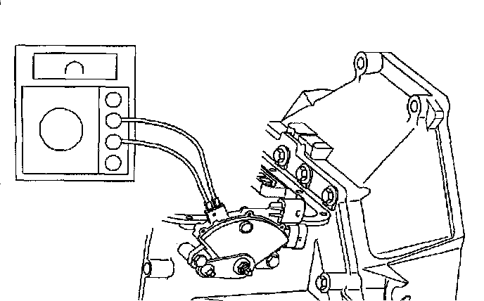
49. Adjust transaxle range switch.
49.1 Place transaxle in D (Drive). Use ohmmeter or continuity tester to check for continuity across terminals on selector switch. Rotate the transaxle range switch from the left fender towards the engine until continuity is achieved.
49.2 Tighten switch-to-case bolts. After switch-to-case bolts have been tightened, recheck continuity.
Torque:
Transaxle Range Switch-to-Case Bolts: 14 Nm (10 ft. lbs.)

50. Clean transaxle case and Valve body cover sealing surfaces with Saturn Choke and Brake Cleaner or equivalent, applied with a clean shop towel.
IMPORTANT: Install new gasket during assembly.
51. Align the Valve body cover gasket on the Valve body cover and install on the transaxle case.
52. When installing the Valve body cover, make sure to properly torque the Valve body cover bolts using the torque sequence shown.
Torque:
Valve body Cover-to-Case Bolts: 12 Nm (9 ft. lbs.)
IMPORTANT: Clean and lubricate fasteners with Saturn Transaxle Fluid. Wipe off excess fluid and install.
53. Verify torque of the Valve body cover bolts to account for gasket relaxation using the torque sequence shown.
Torque:
Valve body Cover-to-Case Bolts: 12 Nm (9 ft. lbs.)

54. Install input shaft to converter O-ring on input shaft (if new O-ring has not already been installed during input shaft assembly). Make sure the O-ring sits in the groove furthest from the input shaft splines.

55. Check converter end play using Converter Endplay Tool SA9163T.
55.1 Install tool down into converter and tighten so that the end of the tool will hold onto the splines inside converter.
55.2 Set up dial indicator to end of tool.
End Play
Standard: 0.00 - 0.60 mm (0.000 - 0.026 inch)

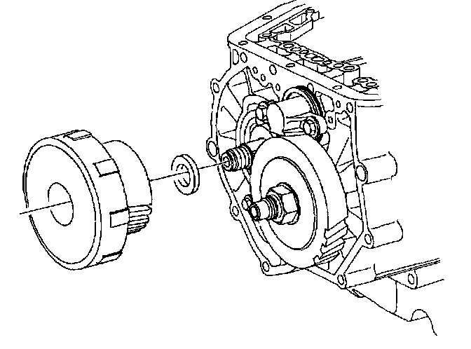
56. Install converter pump hub O-ring seal and install torque converter. Rotate and support converter to align input shaft spline and pump drive slots to converter.
57. Rotate converter so that paint dot is down.
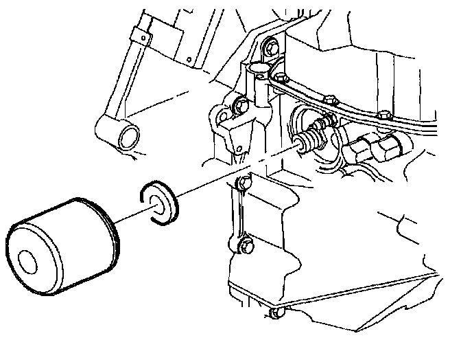
58. Place clean magnet onto new filter.
NOTICE: Install filter hand. Do not use any type of tool that will scratch, dent, or damage filter. If filter is damaged in any way, it must be replaced with a new filter.
59. Using Saturn Transaxle Fluid lube filter seal. Install transaxle pressure filter.
Torque: Follow tightening instructions on filter label.
60. Install transaxle temperature sensor and torque.When installing sensor, use Saturn sealant with Teflon (Saturn P/N 21485278) or equivalent on threads.
Torque:
Transaxle Fluid Temperature Sensor-to-Case: 8 Nm (71 inch lbs.)
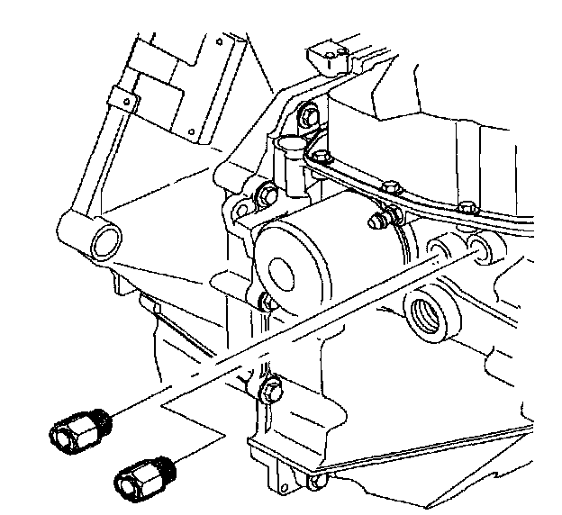
61. Install cooler line fittings if removed.
Torque:
Transaxle Cooler Line Fitting-to-Case: 25 Nm (18 ft. lbs.)
IMPORTANT: Clean and lubricate input speed sensor with Saturn Transaxle Fluid. Wipe off excess fluid.
62. Install input speed sensor and torque.
Torque:
Input Speed Sensor (ISS): 26 Nm (19 ft. lbs.)
63. Install vehicle speed sensor and torque.
Torque:
Output Speed Sensor (OSS): 26 Nm (19 ft. lbs.)
IMPORTANT: Clean and lubricate fasteners with Saturn Transaxle Fluid. Wipe off excess fluid and install.

64. Install transaxle fluid fill tube. Torque retaining bolt.
Torque:
Transaxle Oil Indicator Tube-to-Case Bolt: 12 Nm (9 ft. lbs.)
65. After rebuilding a transaxle the PCM transaxle adaptives should be reset using the service stall system or Scan tool. Follow the learn-in procedure located at beginning of diagnostic charts.