Transaxle Removal
TOOLS REQUIRED- SA9112T Differential End Play Gauge
- SA9132S Lower Control Arm Ball Stud Separator
- SA9165T Oil Cooler Line Flusher

CAUTION: MAKE SURE VEHICLE IS PROPERLY SUPPORTED AND SQUARELY POSITIONED ON HOIST. TO HELP AVOID PERSONAL INJURY WHEN A VEHICLE IS ON A HOIST, PROVIDE ADDITIONAL SUPPORT FOR THE VEHICLE ON THE OPPOSITE END FROM WHICH COMPONENTS ARE BEING REMOVED.
1. Position vehicle on hoist.
2. Disconnect negative battery terminal.

3. Remove air cleaner and duct assembly.
4. Remove air box.

5. Remove transaxle strut-to-midrail bracket fastener.
6. Loosen transaxle strut-to-transaxle bracket fastener and flip transaxle strut out of the way.

7. Disconnect positive battery cable from battery.
8. Remove hold-down retaining nut and screw. Lift off battery hold-down retainer.
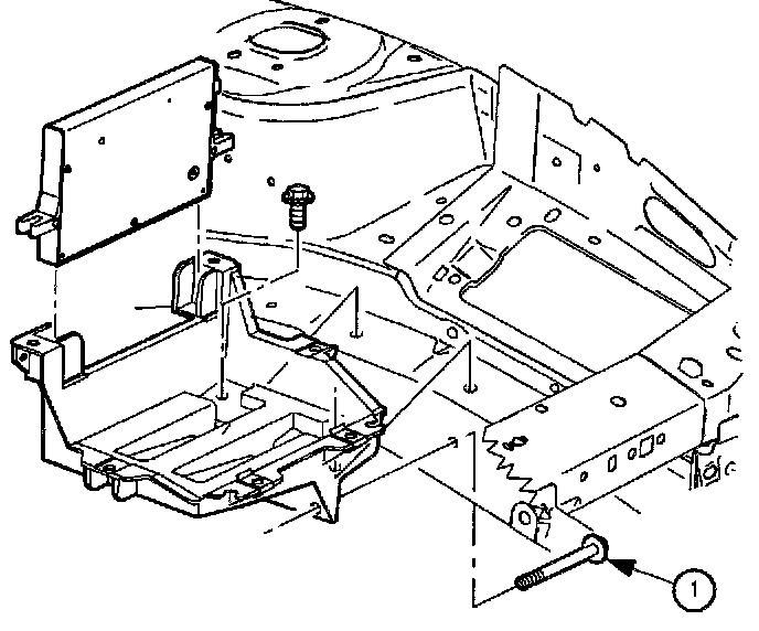
9. Lift the battery out of vehicle, and place in a safe location.
10. Disconnect PCM J2 (black 28-way) harness connector by moving locking device toward fender.
11. Remove PCM attachment bolts.
12. Remove and flip PCM on its side, out of way.
13. Remove battery tray bolts and tray.
13.1 One bolt is located in the fender well.

14. Disconnect the following items:
14.1 Transaxle solenoid harness connector.
14.2 Output speed and input speed sensors harness connectors.
14.3 Transaxle fluid temperature sensor harness connectors.
14.4 Transaxle range switch harness connectors.
14.5 Two ground terminals from top two converter housing bolts.
14.6 Ground wire from transaxle range switch.

15. Remove top two converter housing-to-engine bolts.
IMPORTANT: Note which spark plug wire is removed from which coil towers. The spark plug wires must be connected to the correct coil towers.

16. Disconnect spark plug wires from coil towers.
17. Disconnect EI module harness connector.
18. Remove bolts from EI module.
19. Remove EI module.

20. Wire radiator to upper radiator support to hold the radiator in place as frame is removed.
IMPORTANT: The two cross bars on the engine support have two settings, one for the SOHC (L24) (1) and one for the DOHC (LL0) (2) engine. The setting locations are marked on the bars as shown.

21. Install engine support bar assembly SA9105E.

21.1 Place engine support bar in vehicle as shown. Place the support bar feet on the outer edge of the shock tower.

21.2 Connect bar hooks to engine support brackets.
21.3 Position stabilizer foot on engine block to the right of the engine oil dipstick.
21.4 Adjust hooks and stabilizer to remove looseness.
CAUTION: MAKE SURE VEHICLE IS PROPERLY SUPPORTED AND SQUARELY POSITIONED ON HOIST. TO HELP AVOID INJURY WHEN A VEHICLE IS ON A HOIST, PROVIDE ADDITIONAL SUPPORT FOR THE VEHICLE ON THE OPPOSITE END FROM WHICH COMPONENTS ARE BEING REMOVED.

22. Raise vehicle and drain transaxle fluid.

23. Remove the front wheels.

24. Remove right and left splash shields (LHD shown, RHD similar).

25. Remove front engine splash shield from vehicle. For coupes, remove left and right lower fascia braces.

26. Remove engine strut bracket-to-frame fasteners.

27. Remove transaxle mount-to-frame fastener. (Manual transaxle shown, automatic transaxle similar.)

28. Remove front exhaust pipe-to-manifold fasteners.

29. Remove front exhaust pipe-to-catalytic converter fasteners.
30. Remove exhaust pipe support bracket-to-exhaust pipe fasteners.
31. Remove front exhaust pipe from vehicle.
IMPORTANT: LHD illustration shown first, RHD Domestic illustration shown second.
32. Remove steering gear-to-frame fasteners. (Power steering gear shown, manual steering gear similar.)

33. Support steering gear with safety wire.

RHD Domestic illustration.

34. Remove brake pipe bracket push pin at rear of frame.

35. Remove engine-to-transaxle stiffening brace bolts and remove brace.

36. Remove dust cover to converter housing bolts and remove dust cover.
37. Remove torque converter-to-flywheel bolts.

38. Remove cotter pin from lower ball joints and discard. Loosen nut and back off until top of nut is even with top of threads. (Right side shown, left side opposite.)
39. Repeat for opposite side.
NOTICE: On ABS equipped vehicles, the outer CV joint has a speed sensor ring. Using the incorrect tool or procedure to separate the control arm from the knuckle can damage the ring, resulting in a loss of ABS operation.
NOTICE: Do not attempt to separate the joint using a wedge type tool because the boot may be damaged.
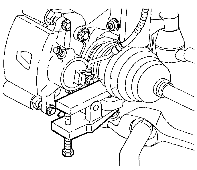
40. Separate ball joint from lower control arm using tool Lower Control Arm Ball Stud Separator SA9132S and remove nut. (Left side shown, right side opposite.)
41. Repeat for opposite side.
IMPORTANT: It will be necessary to pull down on lower control arm to remove castle nut.
NOTICE: Be careful not to damage deflector ring.

42. Separate left side axle from transaxle using a large screwdriver or appropriate pry bar.
43. Remove axle only part way and install axle seal protector Differential End Play Gauge SA91LIT. Use seal protector that was previously used or open up protector at split line and install around axle and into seal. This will protect the seal from being cut by the shaft splines.
44. Separate right side axle from intermediate shaft.

45. On DOHC (LL0) engines, remove intake bracket to intake manifold bolt.
46. Remove intake manifold support bracket-to-intermediate shaft support bolt.
47. Remove two intermediate shaft support to engine block bolts.
48. Carefully slide intermediate shaft out of transaxle.

49. Use the powertrain support dolly and two 4 inch x 4 inch x 36 inch pieces of lumber to support frame on the dolly.
NOTICE: Prior to reinstalling the cooler lines to the transaxle, the cooler lines must be flushed using Oil Cooler Line Flusher SA9165T. This must be done when rebuilding or replacing the transaxle in order to remove all debris.
IMPORTANT: To remove cooler lines from the transaxle squeeze plastic tabs at transaxle connector and pull the line out of connector. The plastic retainer remains on the line.
IMPORTANT: Prepare for a lot of fluid leakage from transaxle cooler line fittings once the lines are disconnected.

50. Disconnect transaxle cooler lines from transaxle. Use a piece of 3/8 inch rubber hose to connect the two cooler lines together. This will prevent oil from dripping and dirt from entering the lines.

51. Remove the four frame-to-body bolts. Carefully lower the frame from the vehicle with the powertrain support dolly.

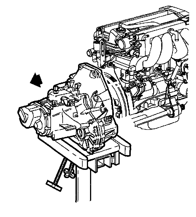
52. Support transaxle securely with jack.
53. Remove two bottom torque converter housing-to-engine bolts.
54. Separate transaxle from engine and lower transaxle.

55. Lower transaxle enough to reach transaxle shifter cable. Disconnect shifter cable from transaxle.
56. Remove shifter cable from converter housing by squeezing release tabs.
57. Lower transaxle from vehicle.