Installation
TOOLS REQUIRED- SA9lOSE Engine Support Bar Assembly
- SA91112T Axle Seal Protector
INSTALLATION
IMPORTANT: When reinstalling the transaxle, tap out the ignition module mounting holes prior to installing the transaxle.
1. Place transaxle securely on jack and position under vehicle. Install axle seal protector into seals on both sides; use Axle Seal Protector SA91112T.
2. Place transaxle in any gear.
3. Raise transaxle into vehicle to align input shaft to the center of the clutch. Guide transaxle into position, rotate back and forth to align input shaft splines to clutch disc.
NOTICE: Make sure input shaft splines line up with the clutch disc splines before tightening clutch housing bolts. Do not use bolts to pull transaxle up to engine.


4. Install two lower clutch housing to engine bolts.
Torque:
Clutch Housing-to-Engine Bolts: 140 Nm (103 ft. lbs.)
5. Remove transaxle jack.

6. Install Axle Seal Protector SA91112T inside seal on transaxle case for left side seal.
NOTICE: Use caution not to damage axle seal when intermediate shaft is installed into transaxle.
7. Install left axle into transaxle.
8. After splines clear the seal protector but before snapping the axle into place, remove the seal protector tool.
9. Install Axle Seal Protector SA91112T inside seal on clutch housing for right side seal. (Left side shown, right side similar.)
NOTICE: Use caution not to damage axle seal when intermediate shaft is installed into transaxle.

10. Install intermediate shaft into transaxle.
11. After splines clear the seal protector but before snapping the axle into place, remove the seal protector tool.
12. Position intermediate shaft support and install two bolts.
Torque:
Intermediate Shaft Support Bracket-to-Engine Bolts: 54 Nm (40 ft. lbs.)
13. Install starter bracket to intermediate shaft bolt, if removed.
Torque:
Intake Manifold Support Bracket-to-Intake Manifold Bolt (LL0): 30 Nm (22 ft. lbs.)
14. On DOHC (LLO) vehicles, position intake manifold support bracket and install intake bracket to intake manifold bolt.
Torque:
Intake Manifold Support Bracket-to-Intake Manifold Bolt (LL0): 30 Nm (22 ft. lbs.)
15. Install intake bracket to intermediate shaft support bolt.
Torque:
Intake Manifold Support Bracket-to-Intermediate Shaft Support Bracket Nut (LL0): 54 Nm (40 ft. lbs.)
16. Install right axle to intermediate shaft.
NOTICE: Take care not to damage rubber boot when installing ball joint to knuckle.

17. Clean and lubricate ball joint threads.
18. Place frame on lift and raise to vehicle and place lower ball joint into knuckles when raising frame up.
IMPORTANT: Make sure that the following parts are correctly positioned when raising frame into vehicle.
- Lower control arm bar studs to knuckle.
- Cooling module support bushings.
- Engine strut frame bracket.
- Transaxle mount.

IMPORTANT: Frame-to-body guide pins must be used to maintain proper alignment. Insert using 9/16 inch round steel rod for alignment pins. Alignment holes are at both front frame mounting locations. Mount studs must be guided into holes in frame as frame is installed.
19. Install two rear frame-to-body fasteners.
IMPORTANT: Do not tighten fasteners at this time.
20. Position frame-to-body at the two front frame-to-body fasteners.
21. Tighten four frame-to-body fasteners.
Torque:
Frame-to-Body Bolts: 210 Nm (155 ft. lbs.)
22. Remove powertrain support dolly.

23. Lower vehicle and remove Engine Support Bar Assembly SA9105E.

24. Install the transaxle strut, transaxle bracket-to-transaxle bolts if removed.
Torque:
Transaxle Strut Bracket-to-Case Bolts: 54 Nm (40 ft. lbs.)

25. Install transaxle strut-to-midrail bracket fastener.
Torque:
Transaxle Strut-to-Midrail Bracket Bolt: 50 Nm (37 ft. lbs.)
26. Tighten transaxle strut-to-transaxle bracket fastener, if removed.
Torque:
Transaxle Strut-to-Transaxle Bracket Bolt: 70 Nm (52 ft. lbs.)
27. Remove cooling module support wire.
IMPORTANT: Run a tap through ignition module mounting holes in transaxle to remove any thread sealant residue.
Tap size 6 x 1.0 mm.

28. Inspect electronic ignition module bolts to make sure mating surfaces are free from grit and dirt. If using new bolts, make sure they are coated with yellow thread sealant. Otherwise apply RTV sealant (P/N 21006236) to bolt threads.
NOTICE: Use extreme care when installing the electronic ignition module bolts make sure the bolt head is seated on the electronic ignition module when the torque specification is reached. If the bolt head is not seated on the electronic ignition module, remove the bolt and tap the hole to clean any debris from the threads.
29. Install electronic ignition module and bolts. (Automatic transaxle shown, manual transaxle similar.)
Torque:
Electronic Ignition Module and Bolts: 8 Nm (71 inch lbs.)

30. Install the top two clutch housing to engine studs. (Automatic transaxle shown, manual transaxle similar.)
Torque:
Transaxle-to-Engine Studs: 100 Nm (74 ft. lbs.)

31. Connect electrical connectors to transaxle.
31.1 Vehicle speed sensor.
31.2 Back-up lamp switch.
31.3 Two ground terminals to top two clutch housing studs.
Torque:
Ground Terminal-to-Top Clutch Housing Studs: 25 Nm (18 ft. lbs.)
31.4 Install vent hose clip to housing if equipped.

32. Connect shifter cables to shift arms and clutch housing. Install cable retainers.

33. Unwire clutch hydraulic system from upper radiator hose. Install two clutch hydraulic system to clutch housing nuts.
Torque:
Clutch Hydraulic Damper Bracket-to-Case Studs: 25 Nm (18 ft. lbs.)
34. Install actuator into clutch housing. Push in and rotate 1/4 turn clockwise. Install retaining clip.
35. Check master cylinder at front of dash connection to be sure it is locked in place.

36. Install battery tray and bolts
36.1 Bolt in fender well (l).
Torque:
Battery Tray-to-Frame Rail Bolts: 10 Nm (89 inch lbs.)
37. Install PCM and PCM attachment bolts.
Torque:
PCM-to-Battery Tray Bolts: 6 Nm (53 inch lbs.)
38. Reconnect PCM J2 (black 28-way) harness connector.

39. Make sure battery tray is clean.
40. Make sure that the battery cable ends are clean and free of corrosion. (Clean with a wire brush.)
41. Make sure that the battery is in good physical condition (e.g., no cracks, or obvious damage) and that the terminals are clean.
42. Install battery carefully in the battery tray; make sure that the terminals do not short against any metal during the installation.
43. Install battery hold-down retainer, locking the battery into the tray. Install and tighten the hold-down retainer nut and screws.
Torque:
Battery Hold Down-to-Battery Tray Fasteners: 9 Nm (80 inch lbs.)
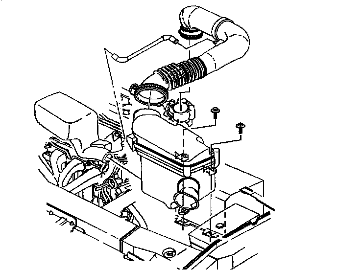
44. Install air cleaner housing and duct assembly.
45. Connect the Intake Air Temperature (IAT) sensor connector.
CAUTION: MAKE SURE VEHICLE IS PROPERLY SUPPORTED AND SQUARELY POSITIONED ON HOIST. TO HELP AVOID PERSONAL INJURY WHEN A VEHICLE IS ON A HOIST, PROVIDE ADDITIONAL SUPPORT FOR THE VEHICLE ON THE OPPOSITE END FROM WHICH COMPONENTS ARE BEING REMOVED.
46. Raise vehicle on hoist.

47. Install transaxle lower mount-to-frame fastener.
Torque:
Transaxle Mount-to-Frame Nut: 50 Nm (37 ft. lbs.)
IMPORTANT: To ensure proper powertrain alignment, make sure that all other mounts have been torqued.

48. Install two engine strut frame bracket-to-frame fasteners.
Torque:
Engine Strut Bracket-to-Frame Nuts: 50 Nm (37 ft. lbs.)

49. Remove steering gear support wire.
50. Install steering gear-to-frame attachment fasteners. (Power steering gear shown, manual steering gear similar.)
Torque:
Steering Gear-to-Frame Bolt & Nut: 50 Nm (37 ft. lbs.)

51. Connect brake pipe-to-frame retainer.

52. Install flywheel housing cover and install flywheel housing cover to clutch housing bolts.
Torque:
Flywheel Housing Cover-to-Clutch Housing Bolts: 11 Nm (8 ft. lbs.)

53. Install engine to transaxle stiffening brace and install brace to engine and transaxle bolts.
Torque:
Engine-to-Transaxle Stiffening Brace Bolts: 54 Nm (40 ft. lbs.)

54. Position exhaust manifold pipe into vehicle.
55. Install exhaust manifold pipe-to-exhaust manifold fasteners and tighten.
Torque:
Exhaust Manifold Pipe-to-Exhaust Manifold Nuts: 31 Nm (23 ft. lbs.)

56. Install the intermediate exhaust pipe-to-three way catalytic converter flange fasteners.
Torque:
Catalytic Converter-to-Intermediate Exhaust Pipe Nuts: 25 Nm (18 ft. lbs.)

57. Install front exhaust pipe clamp support to engine stiffening bracket.
Clamp Support to Engine Stiffening Bracket:
Torque:
Front Exhaust Pipe Hanger-to-Powertrain Stiffening Bracket Bolts: 30 Nm (22 ft. lbs.)
Clamp Support to Front Exhaust Pipe:
Torque:
Front Exhaust Pipe Hanger Strap Clamp: 60 Nm (44 ft. lbs.)
IMPORTANT: After torquing, if necessary, tighten nut additionally to align slot in the nut with the cotter pin hole in the ball joint. Install the cotter pin.

58. Install nut to lower ball joint, and torque.
Torque:
Front Lower Control Arm Ball Stud-to-Steering Knuckle Nut: 75 Nm (55 ft. lbs.)

59. Install right side, left side, and front splash shield to frame fasteners.
60. On Coupes, install right and left lower fascia support to frame J-nuts.
Torque:
Fascia Support-to-Frame Fasteners: 10 Nm (89 inch lbs.)
NOTICE: Before installing wheels, remove rust or corrosion from wheel mounting surfaces and brake rotors/drums. Failure to do so can cause wheel lug nuts to loosen in service.
61. Position wheels onto hubs.
62. Install wheel nuts and tighten in a crisscross pattern. Repeat tightening pattern to be sure torque is correct.
Torque:
Wheel Lug Nuts (In Crisscross Pattern): 140 Nm (103 ft. lbs.)
63. Install drain plug.
Torque:
Transaxle Drain Plug: 30 Nm (22 ft. lbs.)
IMPORTANT: Clean and lubricate fastener with Saturn Transaxle Fluid. Wipe off excess fluid and install.
64. Fill transaxle to proper level using Saturn Transaxle Fluid.
Saturn Transaxle Fluid: 2.5 Liters (2.6 quarts)
CAUTION: THE POSITIVE TERMINAL MUST BE CONNECTED FIRST TO PREVENT ARCING.
65. Install positive battery cable first.
Torque:
Battery Terminal Bolts: 17 Nm (13 ft. lbs.)
IMPORTANT: Attach positive then negative terminal.
66. Install negative battery cable last.
Torque:
Battery Terminal Bolts: 17 Nm (13 ft. lbs.)
67. Perform vehicle alignment.