Water Pump: Service and Repair
WATER PUMP ASSEMBLY- L61TOOLS REQUIRED
J 43651 Water Pump Holding Tool
REMOVAL

1. Drain coolant.
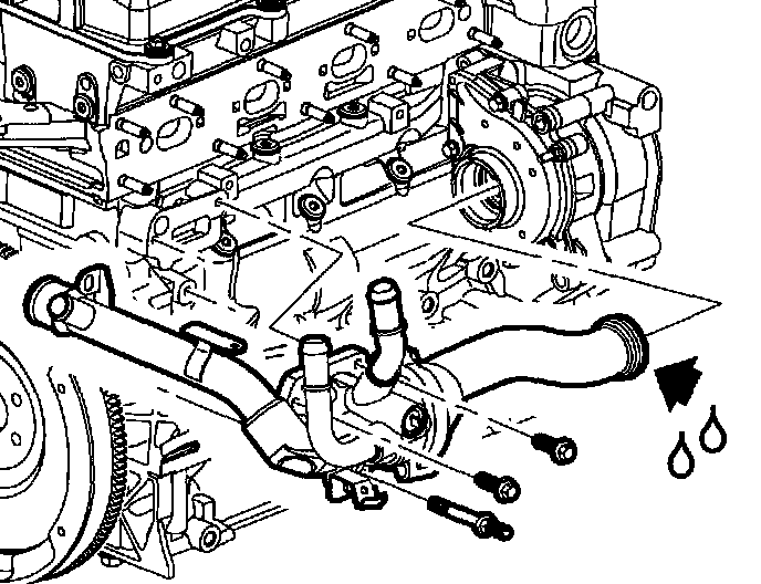
2. Remove thermostat housing pipe-to-cylinder head bolt (near front of engine).
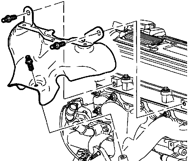
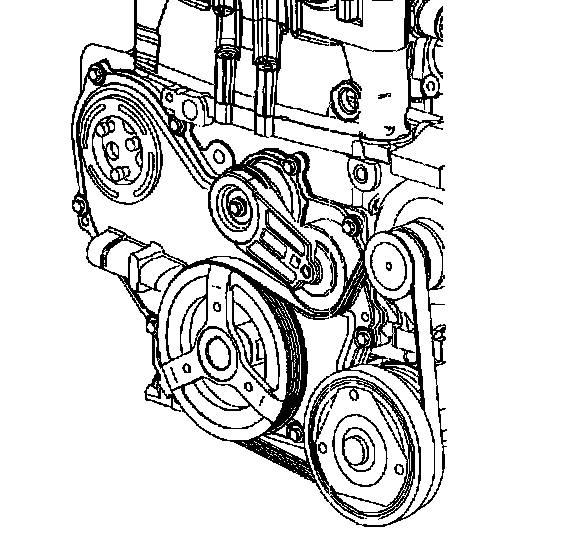
3. Remove exhaust manifold heat shield and bolts.
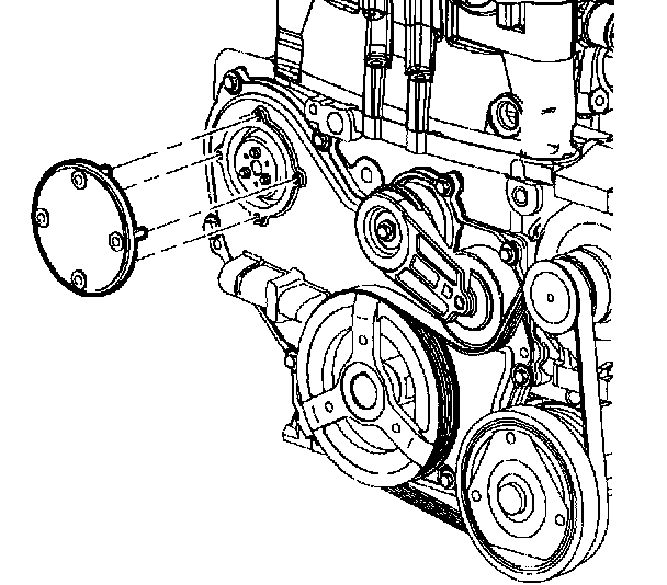
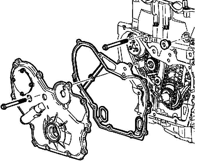
4. Remove water pump access plate from front cover.
5. Remove right hand wheel nuts and wheel assembly.
6. Remove right hand inner push-pins and splash shield.
Important: A drain plug has been provided at the bottom of the water pump assembly for additional coolant drainage from engine block and water pump.
7. Drain coolant from plug at bottom of water pump.
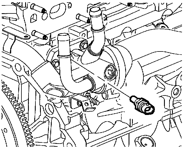
8. Disconnect engine coolant temperature sensor electrical connector.
9. Remove thermostat housing bolts.
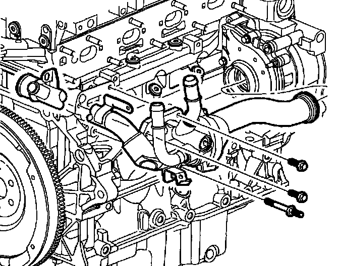
10. Move thermostat housing toward left hand side of vehicle while twisting water feed pipe from rear of the water pump assembly. Leave coolant hoses and thermostat housing cover connected.
11. Remove water feed pipe.
12. Discard water pipe seals.
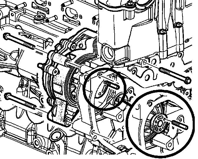
Important: Water pump holding tool supports sprocket and chain during water pump service. The tool must be used or the balance shaft chain must be re-timed.
13. Install the J 43651 into position.
14. Tighten the bolts on water pump holding tool into threads on water pump sprocket.
15. Install access cover bolts that were removed earlier to secure water pump holding tool to front cover assembly.
16. Remove 3 inner water pump sprocket to water pump bolts.
Important: Be sure to remove both water pump retaining bolts from front of engine block.
17. Remove 2 water pump assembly bolts.
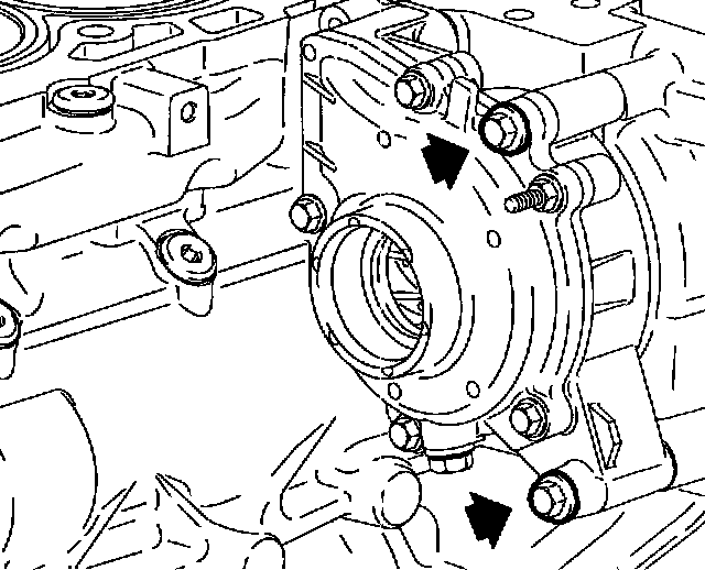
18. Remove rear 2 water pump assembly bolts.
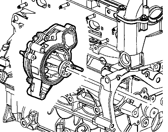
19. Remove water pump assembly and water pump O-seal.
INSTALLATION
Important: Prior to installing the water pump assembly, read the entire procedure. This will help avoid balance shaft chain re-timing and ensure proper sealing.
1. Install new water pump assembly seal.
Important: A guide pin can be created to aid in water pump alignment. Use a M6 m x 6 mm stud. Thread the pin into the water pump sprocket.
2. Using guide pin, align pin with hole in water pump holding tool.
3. Position the water pump assembly against the engine block and hand tighten the water pump bolts.
4. Install inner water pump sprocket bolts. After 2 are snug, remove the guide pin and install the third bolt.
Tighten
Tighten the water pump bolts to 25 N.m (18 lb ft)
5. Tighten water pump bolts.
Tighten
Tighten the water pump sprocket-to-water pump bolts to 10 N.m (89 lb in)
6. Remove the J 43651.
7. Install water pump access plate and bolts.
Tighten
Tighten the water pump access bolts-to-front cover to 10 N.m (89 lb in)
Important: The water feed pipe seals can be lightly lubricated with silicone gel to aid in assembly.
8. Install new O-seal on water feed pipe.
9. Install thermostat housing to block seal onto thermostat housing (if damaged).
10. Install water feed pipe into water pump assembly.
11. Align the water feed pipe to thermostat housing assembly.
12. Seat water feed O-seal by pushing and twisting toward water pump. Take care not to tear or damage O-ring.
13. Water feed pipe has a locating tab to assure proper alignment.
14. Position thermostat housing against engine. Be sure that thermostat housing pipe is properly positioned against the support bracket near the front of engine.
15. Install thermostat housing to block bolts.
Tighten
Tighten thermostat housing-to-block bolts to 10 N.m (89 lb in)
16. Connect electrical connector to coolant temperature sensor.
17. Install right hand inner splash shield and push pins.
18. Install right hand tire assembly and wheel nuts.
Tighten
Tighten wheel nuts to 125 N.m (92 lb ft)
19. Lower vehicle.
20. Install thermostat pipe bracket to cylinder head bolt.
Tighten
Tighten thermostat pipe bracket-to-cylinder head bolt to 8 N.m (71 lb in)
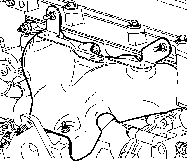
21. Install exhaust manifold heat shield.
22. Install exhaust manifold heat shield bolts.
Tighten
Tighten exhaust manifold heat shield bolts to 25 N.m (18 lb ft)

Important: Vehicle must be level when filling cooling system.
23. Verify drain valve at radiator and water pump are closed.
24. Fill the engine coolant.
25. Verify repair and inspect for any leaks.